Surface acoustic wave resonator, surface acoustic wave oscillator, and surface acoustic wave module unit
- Summary
- Abstract
- Description
- Claims
- Application Information
AI Technical Summary
Benefits of technology
Problems solved by technology
Method used
Image
Examples
first embodiment
[0062]A surface acoustic wave resonator according to a first embodiment of the invention will be described below.
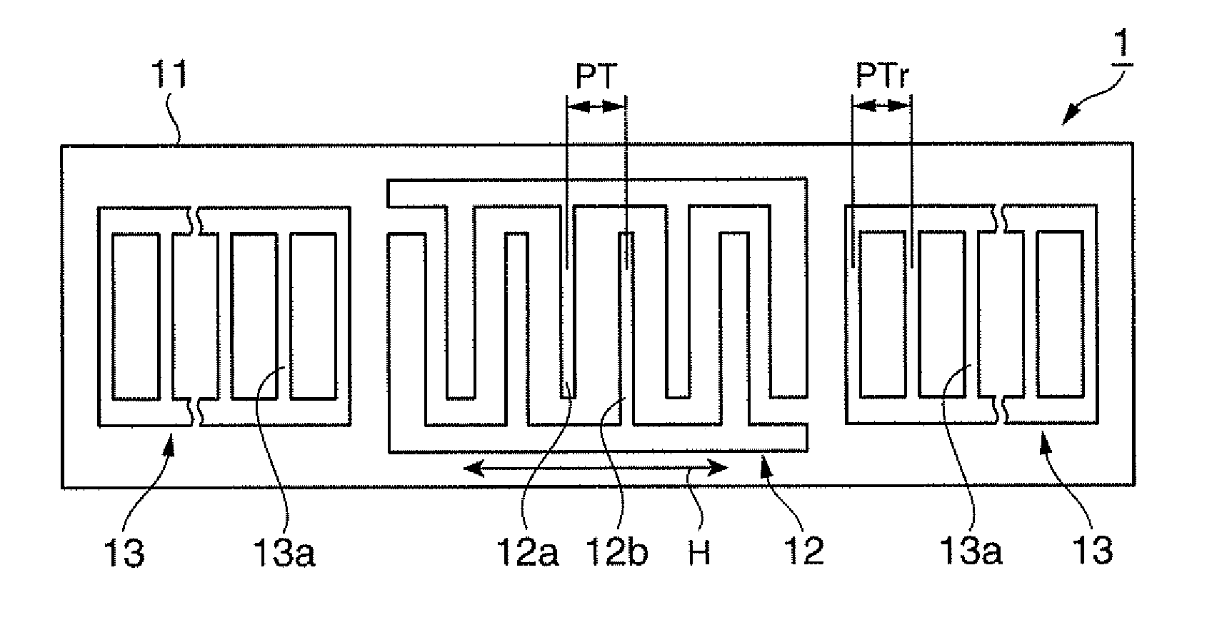
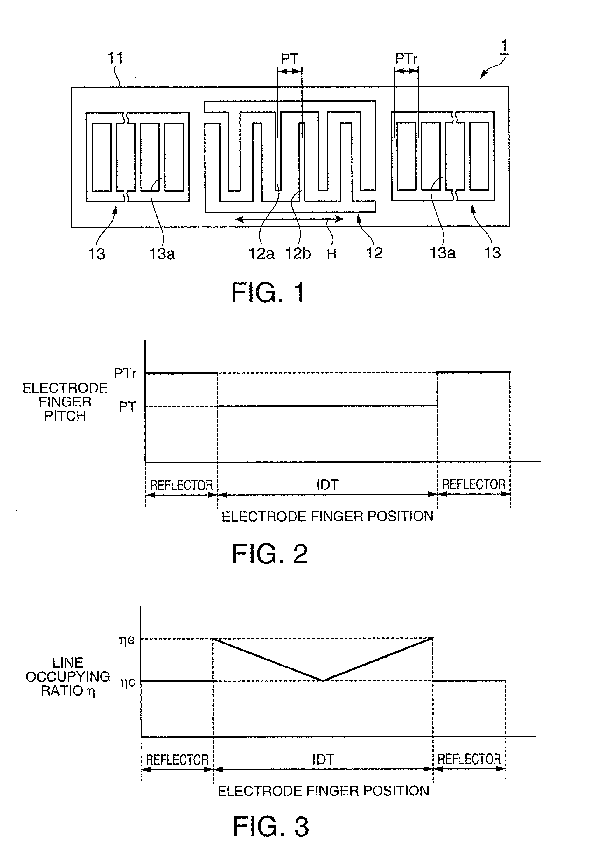
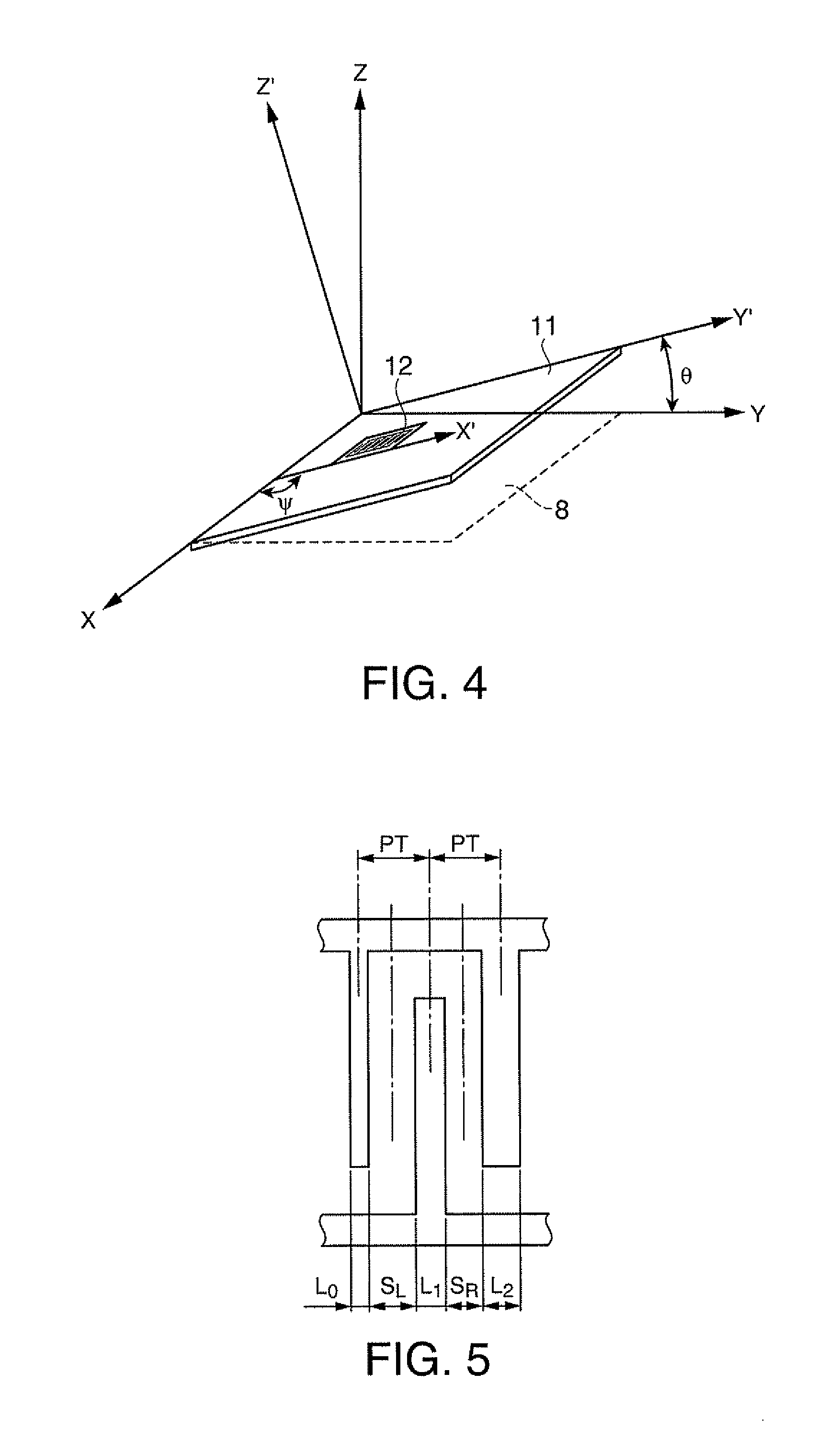
[0063]FIG. 1 is a plan view schematically illustrating the configuration of a surface acoustic wave resonator according to this embodiment. FIG. 2 is a diagram illustrating the relation between an electrode finger position and an electrode finger pitch in the surface acoustic wave resonator according to this embodiment. FIG. 3 is a diagram illustrating the relation between the electrode finger position and a line occupying ratio in the surface acoustic wave resonator according to this embodiment. FIG. 4 is a diagram illustrating a cutout angle of a crystal substrate and a traveling direction of surface acoustic waves. FIG. 5 is a diagram schematically illustrating the line occupying ratio.
[0064]As shown in FIG. 1, the surface acoustic wave resonator 1 includes an IDT 12 having a comb-like electrode and a pair of reflectors 13 disposed with the IDT 12 interposed therebetwe...
modification 1
(Modification 1)
[0094]A modification of the surface acoustic wave resonator according to the first embodiment of the invention will be described below.
[0095]In the first embodiment, the line occupying ratio of the reflectors is set to the same as the line occupying ratio at the center of the IDT. However, in this modification, the line occupying ratio of the reflectors is set to the same as the line occupying ratio at the edges of the IDT.
[0096]FIG. 8 is a plan view schematically illustrating the configuration of a surface acoustic wave resonator according to this modification. FIG. 9 is a diagram illustrating the relation between the electrode finger position and the electrode finger pitch in the surface acoustic wave resonator according to this modification. FIG. 10 is a diagram illustrating the relation between the electrode finger position and the line occupying ratio in the surface acoustic wave resonator according to this modification.
[0097]As shown in FIG. 8, a surface acoust...
modification 2
(Modification 2)
[0111]Another modification of the surface acoustic wave resonator according to the first embodiment of the invention will be described below.
[0112]In the first embodiment, the line occupying ratio of the reflectors is set to the same as the line occupying ratio at the center of the IDT. However, in this modification, the line occupying ratio of the reflectors is set to greater than the line occupying ratio at the edges of the IDT.
[0113]The configuration of the surface acoustic wave resonator according to this modification is almost the same as Modification 1 and thus will not be described in detail but in brief.
[0114]FIG. 12 is a diagram illustrating the relation between an electrode finger position and an electrode finger pitch in a surface acoustic wave resonator according to this modification. FIG. 13 is a diagram illustrating the relation between the electrode finger position and the line occupying ratio in the surface acoustic wave resonator according to this mo...
PUM
 Abstract
Description
Claims
Application Information
 - R&D
- Intellectual Property
- Life Sciences
- Materials
- Tech Scout
- Unparalleled Data Quality
- Higher Quality Content
- 60% Fewer Hallucinations
Browse by: Latest US Patents, China's latest patents, Technical Efficacy Thesaurus, Application Domain, Technology Topic, Popular Technical Reports.
© 2025 PatSnap. All rights reserved.Legal|Privacy policy|Modern Slavery Act Transparency Statement|Sitemap|About US| Contact US: help@patsnap.com


