Digitally controlled circulator and radio frequency identification reader having the same

a radio frequency identification and circulator technology, applied in the field of digital control circulators, can solve the problems of increasing the dimensions occupied by the antenna, not suitable for small, high-integrated and inexpensive readers, and difficult to apply the structure to small devices such as cellular phones, and achieve the effect of less loss

Inactive Publication Date: 2007-05-03
ELECTRONICS & TELECOMM RES INST
View PDF4 Cites 29 Cited by
  • Summary
  • Abstract
  • Description
  • Claims
  • Application Information

AI Technical Summary

Benefits of technology

[0019] It is an object of the present invention to provide a circulator and a radio frequency identification (RFID) reader having the circulator, the circulator having less loss in transmitting and receiving a radio frequency (RF) signal and being digitally controlled.

Problems solved by technology

However, since the circulator 120 is made up of a great-sized magnetic material which cannot be fabricated by a general integrated circuit (IC) semiconductor process, it is not suitable for small, highly integrated, and inexpensive readers.
In addition, when the structure having the two antennas 140 and 141 as described above is applied to the system using a UHF band, dimensions occupied by the antennas increase, so that it is difficult to apply the structure to small devices such as cellular phones.
However, in the circulator comprising the transistors, the sensitivity of the receiver deteriorates due to noise generated at the transistors T1 and T2, and the transmitter barely processes a high output signal of more than 20 dBm without distortion due to a nonlinearity characteristic.
However, it is known that the active circulator has worse characteristics than a passive circulator due to a very high noise figure (NF) (See “IEEE Trans.
The equal distribution of the signal received through the antenna to the transmitter and the receiver, however, causes an insertion loss of 3 dB.
This insertion loss increases the NF, deteriorating receive sensitivity, and increases a bit error rate (BER).
Therefore, the passive circulator based on the Wilkinson power splitter is difficult to apply to an RFID system requiring a very low BER.

Method used


Image

  • Digitally controlled circulator and radio frequency identification reader having the same
  • Digitally controlled circulator and radio frequency identification reader having the same
  • Digitally controlled circulator and radio frequency identification reader having the same

Examples


Embodiment Construction

[0038] Hereinafter, an exemplary embodiment of the present invention will be described in detail. However, the present invention is not limited to the embodiments disclosed below, but can be implemented in various types. Therefore, the present embodiment is provided for complete disclosure of the present invention and to fully inform the scope of the present invention to those ordinarily skilled in the art.

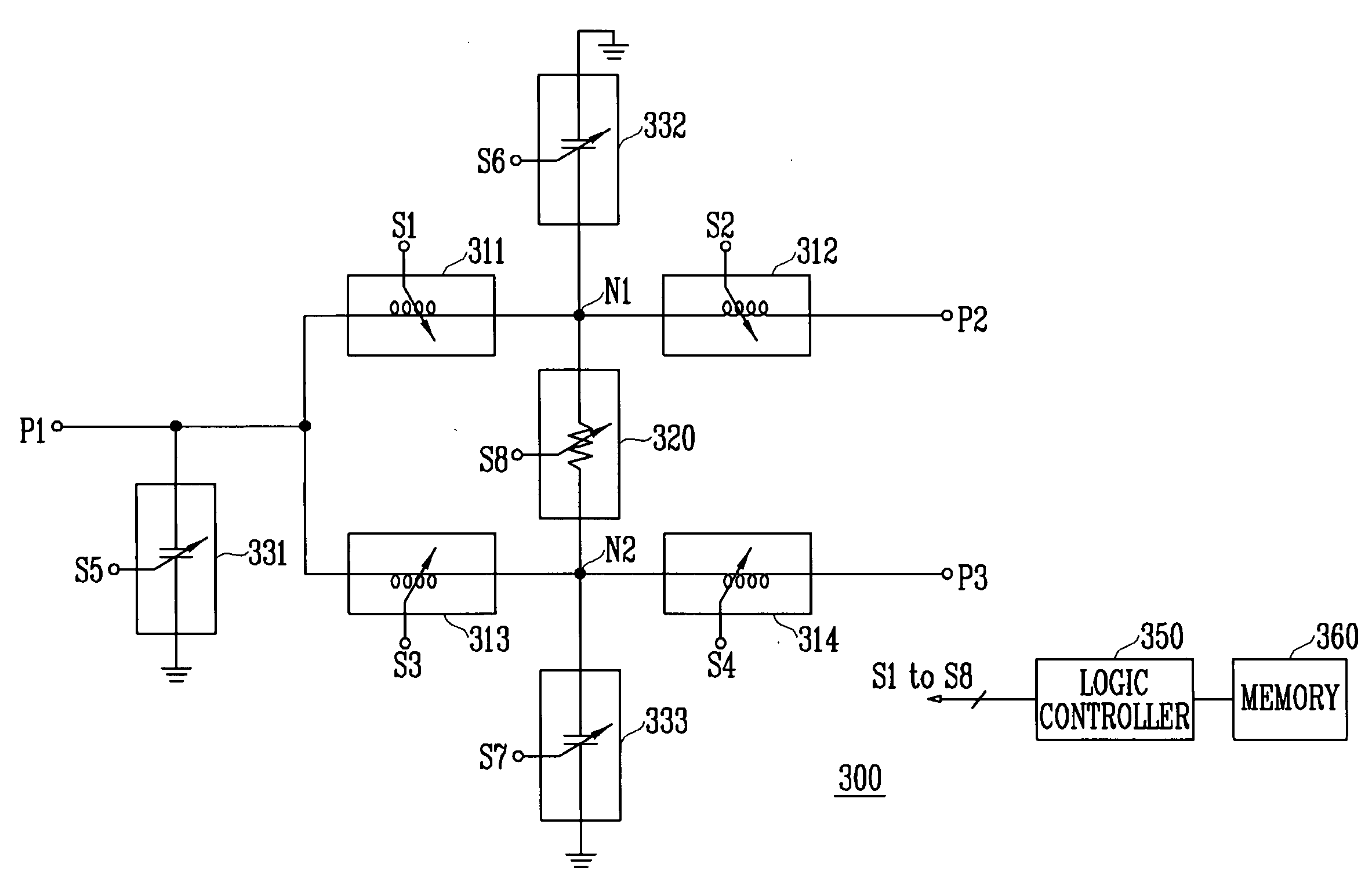
[0039]FIG. 3 is a circuit diagram illustrating a digitally controlled circulator according to an exemplary embodiment of the present invention.

[0040] The circulator 300 includes a first terminal P1 connected to an antenna, a second terminal P2 connected to a transmitter, and a third terminal P3 connected to a receiver. Between the first terminal and the second terminal, first and second variable inductors 311 and 312 are connected in series. And between the first terminal P1 and the third terminal P3, third and fourth variable inductors 313 and 314 are connected in series. A var...


PUM


Abstract

Provided are a digitally controlled circulator and a radio frequency identification (RFID) reader having the circulator. A power splitter is composed of lumped elements and the values of the elements are digitally changed using switching means, in which the transmission loss of a signal is controlled according to whether the reader is in a transmission state or a reception state. Therefore, the loss can be minimized, and the circulator can be miniaturized and priced down by an integrated circuit (IC) semiconductor process and mounted in a mobile terminal such as a cellular phone.

Description

CROSS-REFERENCE TO RELATED APPLICATION [0001] This application claims priority to and the benefit of Korean Patent Application No. 2005-104852, filed Nov. 3, 2005, the disclosure of which is incorporated herein by reference in its entirety. BACKGROUND [0002] 1. Field of the Invention [0003] The present invention relates to a circulator that is applied to a radio frequency (RF) transceiver system and a radio frequency identification (RFID) reader having the circulator, and more particularly, to a digitally controlled circulator that can be mounted in a small portable terminal such as a cellular phone and an RFID reader having the circulator. [0004] 2. Discussion of Related Art [0005] RFID is a technology that reads information from a tag or writes information to a tag using an RF and is used to identify, trace and manage goods, animals, people and so forth to which a tag is attached. An RFID system based on the RFID technology comprises a tag or a transponder that has unique identifi...

Claims


Application Information

Patent Timeline
Patent Type & Authority Applications(United States)
IPC IPC(8): H01P1/32
CPCH03H7/52G06K17/00H01P1/38
Inventor HYUN, SEOK BONGPARK, KYUNG HWANKANG, TAE YOUNGPARK, SEONG SU
Owner ELECTRONICS & TELECOMM RES INST
Why Eureka
Try Eureka