Head for thermal assisted magnetic recording device, and thermal assisted magnetic recording device

a recording device and magnetic recording technology, applied in special recording techniques, recording information storage, instruments, etc., can solve the problems of recording information loss due to thermal fluctuations, recording bits cannot be formed in the medium, etc., and achieve the effect of reducing background ligh

Inactive Publication Date: 2007-05-03
HITACHI LTD
View PDF6 Cites 38 Cited by
  • Summary
  • Abstract
  • Description
  • Claims
  • Application Information

AI Technical Summary

Benefits of technology

[0011] A second scatterer may be placed near a vertex of the scatterer at which the optical near-field is generated. In this case, it is preferable that an end portion of the scatterer, which is positioned opposite to the vertex where the optical near-field is generated, be placed to substantially coincide with an end portion of the magnetic pole. If the second scatterer is placed in this way, since the second scatterer has the function of attracting the energy of incident light into the bottom of magnetic pole, it becomes possible to generate a strong optical near-field even in the case where the vertex of the scatterer for generating the optical near-field is positioned under the magnetic pole. It should be noted that the second scatterer may be a shield for reducing background light. The magnetic pole placed over the scatterer may be placed so as to be coupled to a main pole of a single pole transducer used in a magnetic recording device.

Problems solved by technology

In conventional magnetic recording devices, when recording density becomes 1 Tb / in2 or more, recording information loss due to thermal fluctuations becomes a problem.
However, since there are limitations on the intensity of a magnetic field capable of being generated in a recording head, a recorded bit cannot be formed in the medium if the coercivity thereof is increased too much.

Method used


Image

  • Head for thermal assisted magnetic recording device, and thermal assisted magnetic recording device
  • Head for thermal assisted magnetic recording device, and thermal assisted magnetic recording device
  • Head for thermal assisted magnetic recording device, and thermal assisted magnetic recording device

Examples


example 1

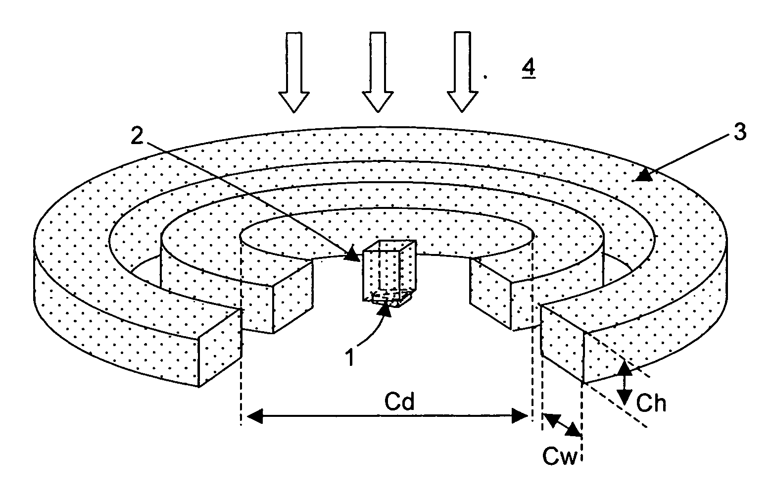
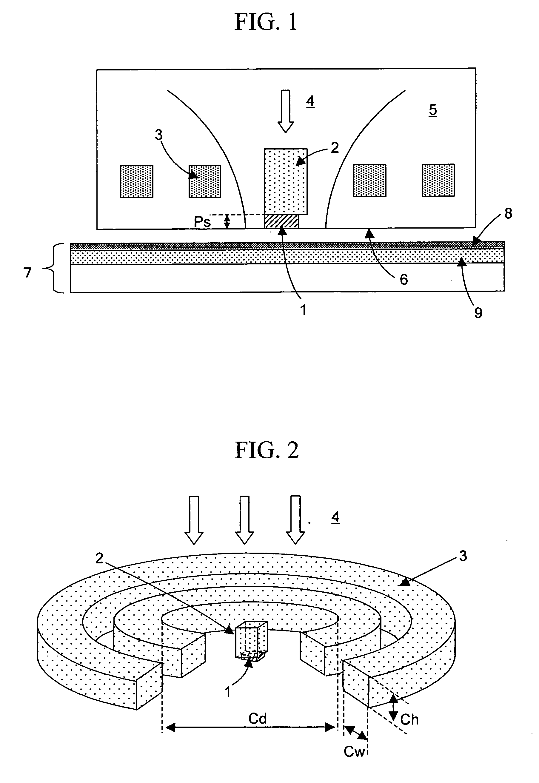
[0050] In a head for a thermal assisted magnetic recording device of the present invention, as shown in FIGS. 1 and 2, a conductive scatterer 1 for generating an optical near-field was placed in a bottom portion of a slider 5 to serve as a base of the head, and coils 3 for generating a magnetic field were placed above the scatterer 1 (on the opposite side thereof from a medium 7). Furthermore, in order to increase the intensity of the magnetic field at a position where the optical near-field is generated, a magnetic pole 2 was placed over the scatterer. Here, “being placed over the scatterer” means that the midpoint of the line connecting a point on the scatterer at which the optical near-field is generated and an end portion opposite thereto is arranged to be positioned under the magnetic pole.

[0051] The direction in which light enters the scatterer is arbitrary, and it may come from above or below the scatterer 1 or in a lateral or an oblique direction relative to the scatterer 1...

example 2

[0066] Next, examples will be described for the case where the shape of the scatterer is changed.

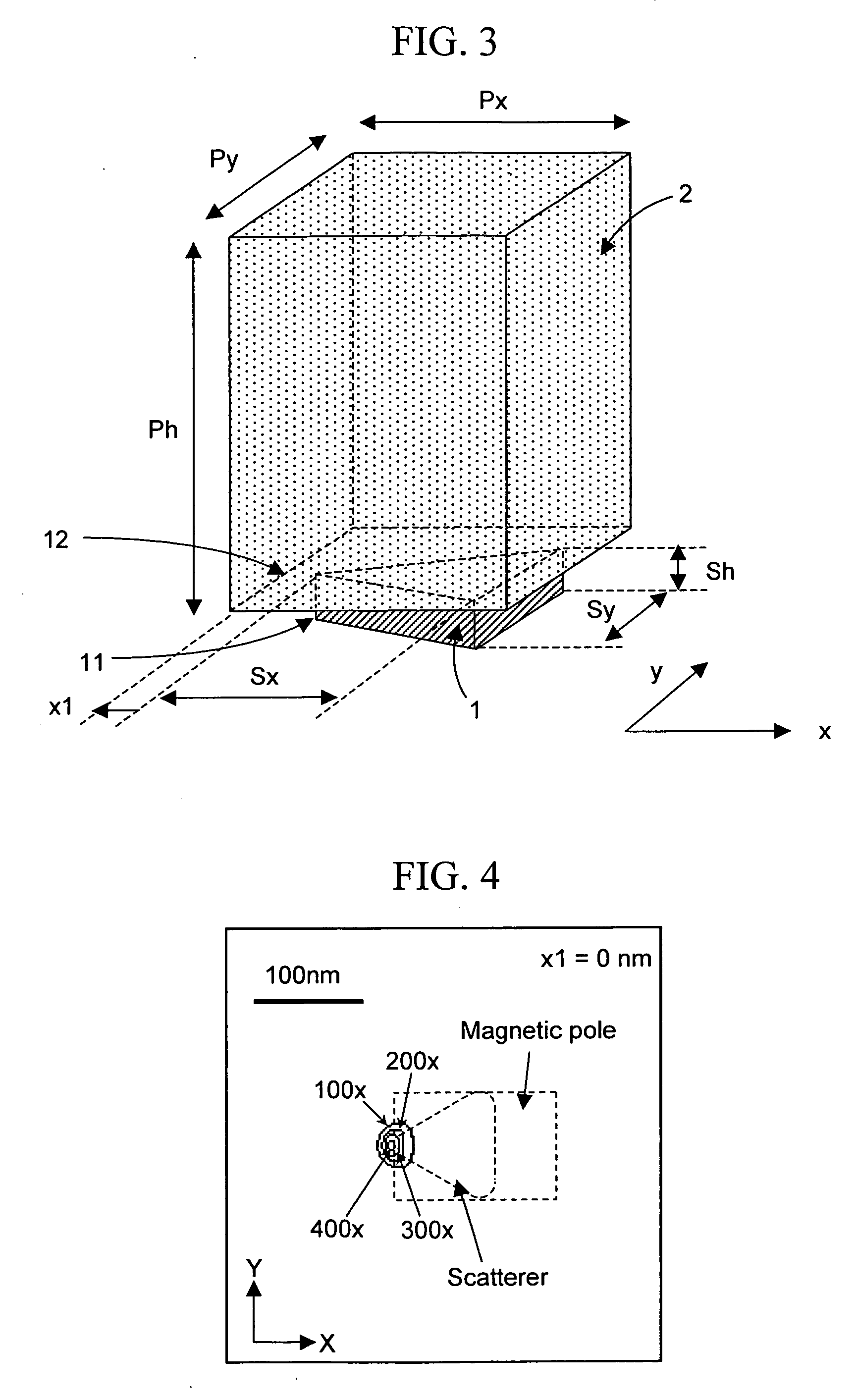
[0067] The shape of the scatterer may be a trapezoid, a rectangle, an ellipse, a sphere, or the like instead of a triangle. FIG. 14A shows an example of a case where the shape of the scatterer is a trapezoid. The material of the scatterer 1 was gold. The length Sx thereof was set at 100 nm, the upper base length S2 thereof was set at 40 nm, the lower base length S1 thereof was set at 100 nm, and the thickness Sh thereof was set at 30 nm. The shape of the magnetic pole 2 was also a trapezoid, and x- and y-direction dimensions thereof were the same as those of the scatterer 1. The scatterer 1 and the magnetic pole 2 were placed one on top of the other. The thickness Ph of the magnetic pole 2 was set at 500 nm. The material of the magnetic pole 2 was FeCo alloy. Light which was polarized in the x direction and had a wavelength of 780 nm was made incident from above, thus generating an opti...

example 3

[0069] Next, examples will be described for cases where the scatterer is of a soft magnetic material. The material of the scatterer may be changed to a soft magnetic material. FIGS. 16A and 16B show an example of a case where the material of the scatterer is FeCo alloy and where the scatterer also serves as a magnetic pole. Since FeCo alloy has conductivity, an optical near-field can be generated at the vertex 11 as in the case where metal such as gold is used. This can reduce the distance between the magnetic pole (scatterer) and the medium, and can therefore increase the intensity of the magnetic field applied to the medium.

[0070] In this example, the shape of a scatterer 17 made of a soft magnetic material was a triangle. Adjusting the length Sx of the scatterer 17 so that plasmon resonance occurs can increase the intensity of the optical near-field generated at the vertex 11. In this example, Sx was set at 140 nm. The thickness Sh of the scatterer was set at 500 nm, and the ang...


PUM


Abstract

The aim of the present invention is to apply an intense magnetic field to a portion where an optical near-field is generated by a thermal assisted magnetic recording head with a scatterer having conductivity as an optical near-field generating element. To this end, a scatterer for generating an optical near-field is formed in a bottom portion of a slider, and a magnetic field is applied thereto using a coil. In order to increase the intensity of the magnetic field, a magnetic pole made of a soft magnetic material is formed over the scatterer.

Description

CLAIM OF PRIORITY [0001] The present application claims priority from Japanese application JP 2005-318511 filed on Nov. 1, 2005, the content of which is hereby incorporated by reference into this application. BACKGROUND OF THE INVENTION [0002] 1. Field of the Invention [0003] The present invention relates to a head for a thermal assisted magnetic recording device, and a thermal assisted magnetic recording device. [0004] 2. Description of the Related Art [0005] In recent years, a thermal assisted magnetic recording system has been proposed as a recording system which realizes a recording density of not less than 1 Tb / in2 (H. Saga, H. Nemoto, H. Sukeda, and M. Takahashi, Jpn. J. Appl. Phys. 38, Part 1, 1839 (1999)). In conventional magnetic recording devices, when recording density becomes 1 Tb / in2 or more, recording information loss due to thermal fluctuations becomes a problem. In order to prevent this, the coercivity of a magnetic recording medium needs to be increased. However, si...

Claims


Application Information

Patent Timeline
Patent Type & Authority Applications(United States)
IPC IPC(8): H01H37/00
CPCG11B5/02G11B5/1272G11B5/3116G11B5/314G11B11/10536G11B2005/0002G11B2005/0021
Inventor MATSUMOTO, TAKUYAAKAGI, FUMIKO
Owner HITACHI LTD
Why Eureka
Try Eureka