
Multi-user terminal services accelerator

Inactive Publication Date: 2007-05-03
MICROSOFT TECH LICENSING LLC
View PDF58 Cites 150 Cited by
  • Summary
  • Abstract
  • Description
  • Claims
  • Application Information

AI Technical Summary

Benefits of technology

[0015] The present invention provides an efficient architecture for a host or server system in a multi-user computer system including one or more Remote Terminals capable of interactive graphics and video. The host computer system generally manages applications and performs server based computing. Each RT has its own keyboard, mouse and display and possibly other peripheral devices. The RTs provide individual users with access to the applications on the server as well as a rich graphical user interface.
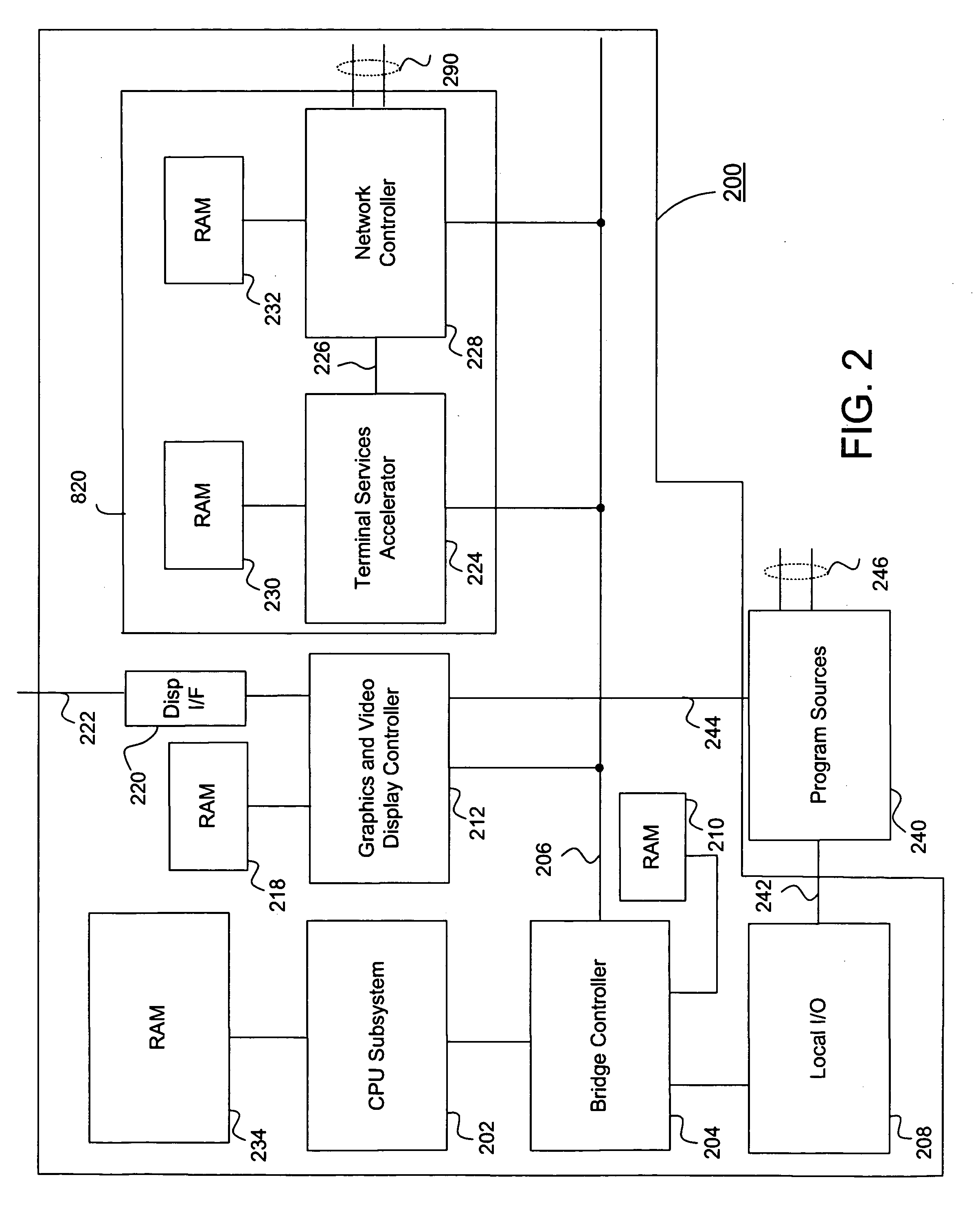
[0016] In the first preferred embodiment, the host system includes an auxiliary processor referred to as a Terminal Services Accelerator (TSA) that offloads the computational tasks of managing a remote graphics protocol for each RT. The TSA allows a multi-user host computer to economically scale to adaptively support numerous and different RTs that may be networked over a variety of different bandwidth solutions. The TSA may include processing elements in the form of configurable processors, Digital Signal Processors (DSPs) or hardware blocks to best perform the offload from the host, and further, do an improved job of supporting a variety of terminals. The offload may include encapsulation of graphics commands into network packets, encoding of different blocks of data so that the communication channel may be more efficiently used, and tracking the cached data for each RT. There is likely to be a local graphics processor in the host system for supporting a local terminal, but it is not part of the support system for the RTs. The TSA can process local graphics to provide remote KVM management capabilities.
[0020] The system may feed back network information from the various wired and wireless network connections to the host system CPU, TSA and data encoding systems. The host system uses the network information to affect the various processing steps of producing RT updates and, based on the network feedback, can vary the frame rate and data encoding for different RTs. Additionally, for systems that include noisy transmission channels as part of the network, the encoding step may be combined with forward error correction protection in order to prepare the transmit data for the characteristics of the transmission channel. The combination of these steps maintains an optimal frame rate with low latency for each of the RTs. The TSA may be implemented as a separate subsystem or combined with other offload and acceleration processing such as the network processor, security processor, XML accelerator, iSCSI processor or any combination of these.
[0021] Therefore, for at least the foregoing reasons, the present invention effectively implements a flexible multi-user RT system that utilizes various heterogeneous components to facilitate system interoperability and functionality. The present invention thus efficiently implements an enhanced multi-user RT system.

Problems solved by technology

However, for multi-user systems, the approach of using the main CPU at the host to improve the performance for any one user has significant limitations.
Computational resources such as main memory and CPU cycles that are used for optimizations for one user may reduce the ability to support the workload for additional users.
With host computers ever increasing their performance by including multiple CPUs and CPUs that have multiple processor cores, the limitation of a single user to a single computer makes less and less economic sense.
However, an increased complexity may be required for a multi-user host computer to effectively manage, control and deliver rich application performance for the variety of RT devices that an organization may have.

Method used


Image

  • Multi-user terminal services accelerator
  • Multi-user terminal services accelerator
  • Multi-user terminal services accelerator

Examples


Embodiment Construction

[0033] The present invention relates to an improvement in multi-user Remote Terminal (RT) computer systems. While the described embodiments relate to multi-user RT computer systems, the same principles and features could be equally applied to other types single user systems and other types of thin clients.

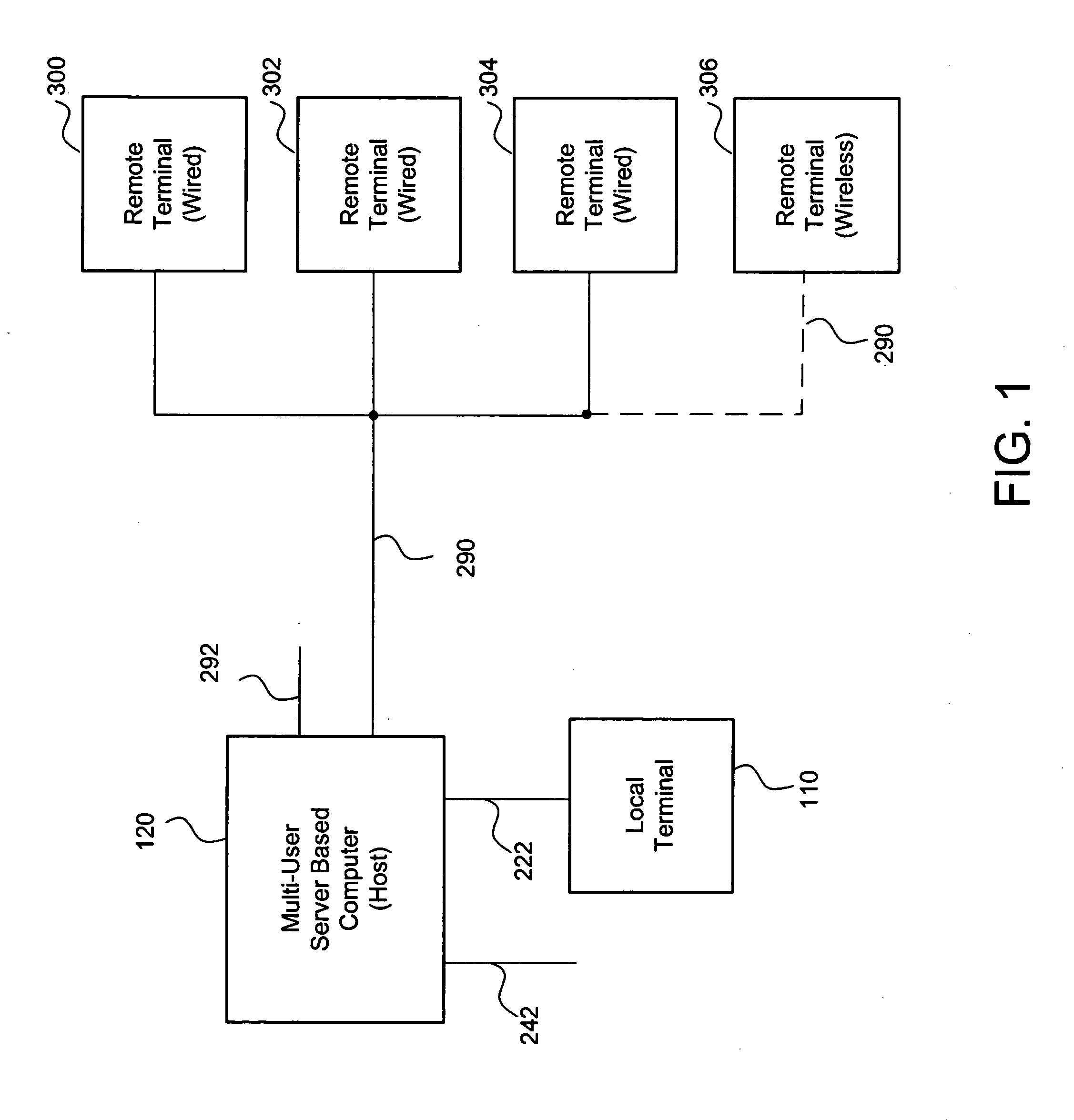
[0034] Referring to FIG. 1, the invention provides an efficient architecture for a multi-user computer system 100. A Multi-User server based computer 120, referred to as the “Host 120,” processes applications for multiple users each utilizing some form of a Remote Terminal. A local terminal 110 is included primarily for a single user or for administrative tasks, and the Host 120 produces display update network streams over wired network(s) 290 to each of RTs 300, 302, 304, etc., or over a wireless network 290 to display(s) 306. Users at the RTs are able to time-share the host computer 120 as if it were their own local computer and have complete support for all types of graphics, t...


PUM


Abstract

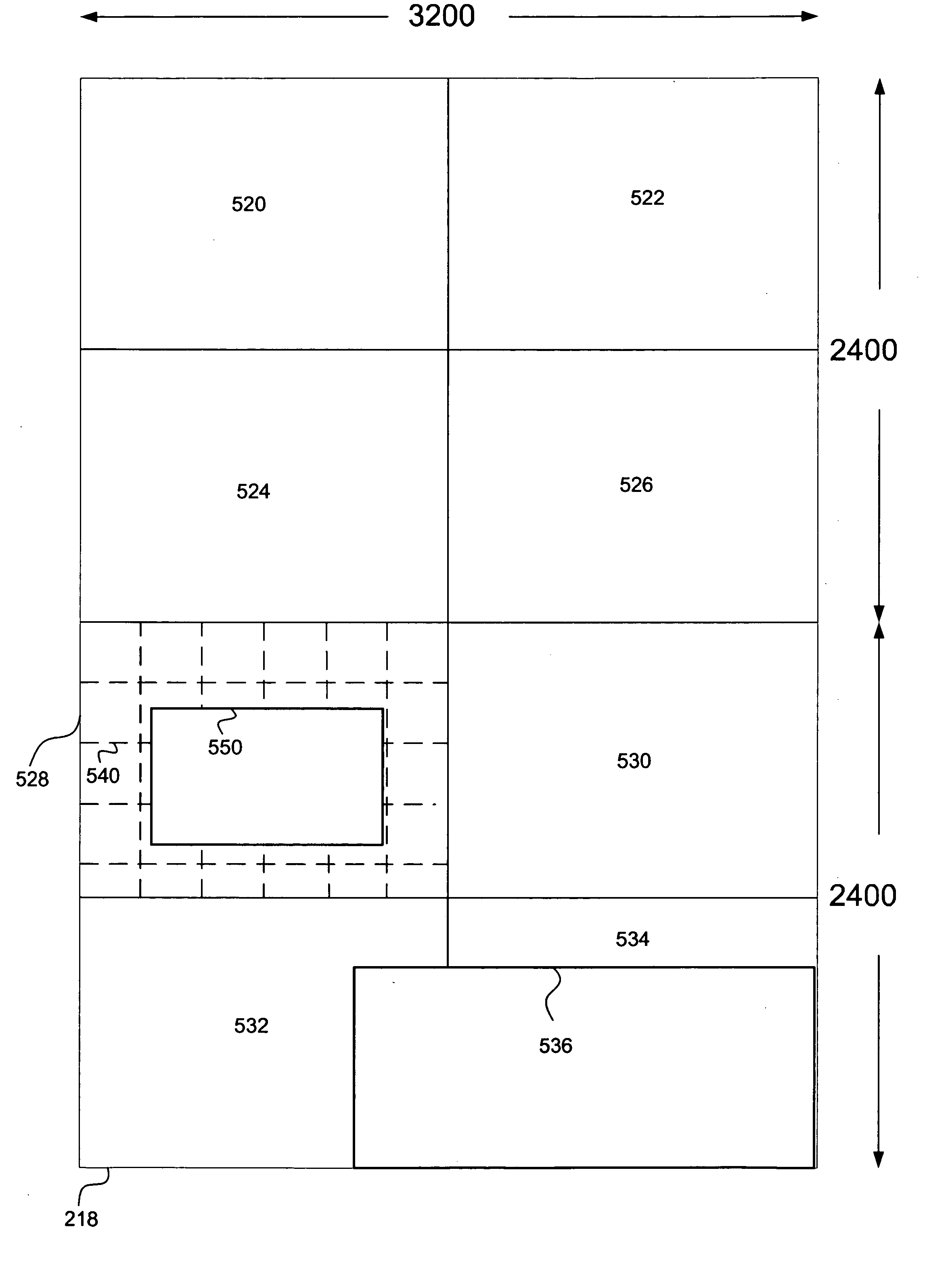
A multi-user host computer system comprises a host computer that processes applications and the desktop environments for multiple remote terminals. The host computer includes a terminal services offload processor to supplement the processing of the host CPU. For each remote terminal, the terminal services offload processor may improve the video and graphics performance and allow the multi-user host computer system to more efficiently support multiple users. The host computer may include a graphics processor that manages a virtual display for each remote terminal and provides selective updates of sub frame data. Where appropriate, the sub frame data is encoded and transmitted over the network to the remote terminals. Video data streams are also optimized by the terminal services offload processor and optimized for the intended remote terminals and their respective network connections. The terminal services offload processor may be implemented in programmable hardware and may be a separate subsystem or may also be used to perform other offload tasks.

Description

BACKGROUND OF THE INVENTION [0001] 1. Technical Field [0002] The present invention relates generally to a multi-user host computer system, and relates more particularly to effective terminal services support for remote clients. [0003] 2. Discussion of Background Art [0004] Developing efficient multi-user host computer systems is a significant objective for contemporary system designers and manufacturers. [0005] Conventional computer systems may utilize a local display device to display output directly to one user. The local display device is typically positioned close to the computer system because of restrictions imposed by various physical connections that electrically couple the display device to the output of the computer system. Some computer systems may support a second display device that has similar proximity restrictions due to the physical connections. [0006] Remote users require the additional flexibility of choosing an appropriate viewing location and network connection ...

Claims


Application Information

Patent Timeline
IPC IPC(8): G06T1/00
CPCG06F3/1431G06F3/1462G06T1/20G06T15/005G06T2200/16G09G5/363G09G2320/0252G09G2370/025G06T1/00G06F1/00
Inventor MARGULIS, NEAL D.
Owner MICROSOFT TECH LICENSING LLC
Learn More