Light emitting device

a technology of light emitting device and light source, which is applied in the direction of light and heating apparatus, semiconductor devices for light sources, laminated elements, etc., can solve the problems of difficult to improve the productivity of light emitting device and heat accompanying emission, and achieve high output requirements, easy assembly and downsizing, and high radiation performance

Inactive Publication Date: 2007-05-03
TOYODA GOSEI CO LTD
View PDF14 Cites 45 Cited by
  • Summary
  • Abstract
  • Description
  • Claims
  • Application Information

AI Technical Summary

Benefits of technology

[0048] According to the invention, a light emitting device can be easy assembled and downsized while having a high radiation performance to meet the high output requirement.
[0049] Particularly, in the above invention (1), the radiator can be easy assembled by using the plate members which is easy available and workable. Thus, the light emitting device can be downsized without any limitation in its processing.
[0050] Further, in the above invention (2), in addition to the advantage of the invention (1), the reflecting mirror part reflects a light emitted from the light source and leads the light along the surface of the radiation plates as a component of the radiator through spaces formed between the radiation plates so that the light can be led to a side of a back surface of the light source while suppressing the light loss.

Problems solved by technology

According to this, recently, light emitting devices using LEDs of various types such as LED of a high output type and LED of a large light amount type have been proposed, but a problem of the heat accompanying the emission have become evident.
Therefore, it becomes an important issue that how to ensure a high radiation performance in order to realize a light emitting device using LED of a high output type.
However, in the light emitting device shown in the patent document there are the following problems.
(1) It is necessary to conduct a positioning for inserting and fixing of the radiation plates appropriately when the radiator is formed by assembling the radiation plates so that the assembling work becomes troublesome and then it becomes difficult to improve a productivity of the light emitting device.

Method used


Image

  • Light emitting device
  • Light emitting device
  • Light emitting device

Examples


first embodiment

[0093] Composition of Light Emitting Device

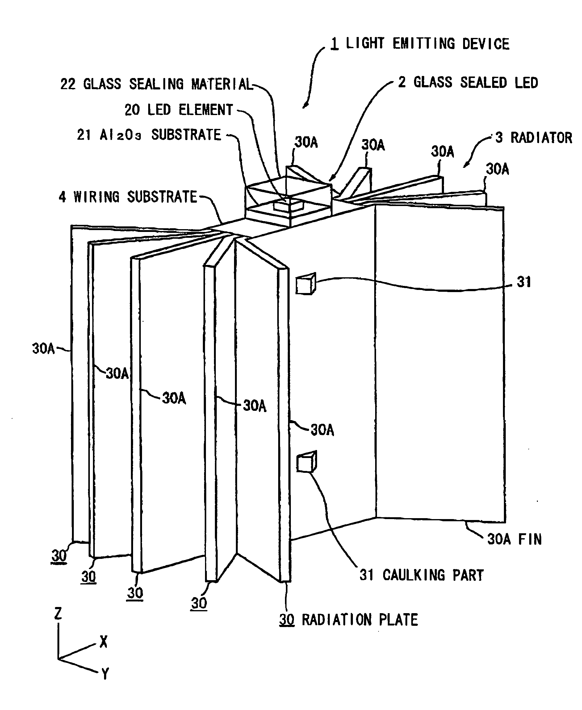
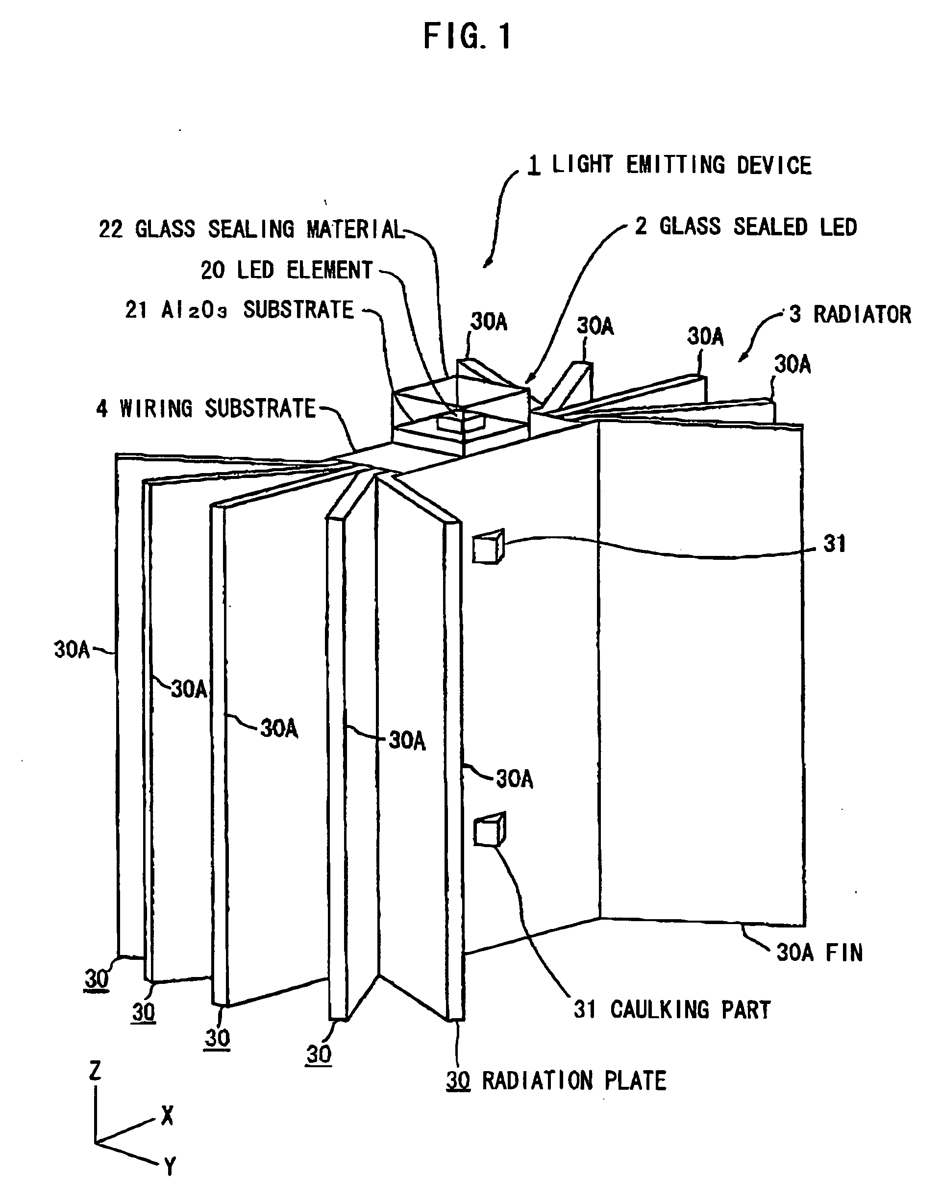
[0094]FIG. 1 is a perspective view schematically showing a light emitting device in the first preferred embodiment according to the invention. In explaining the following preferred embodiment, hereinafter, a width direction of the light emitting device 1 is defined as X, a length direction is defined as Y, and a height direction is defined as Z.

[0095] As shown in FIG. 1, the light emitting device 1 comprises a glass sealed LED 2 formed by sealing a LED element 20 with a glass, and a radiator 3 comprising plate members 30 composed of a thermally-conductive material and integrated at a caulking part 31. The glass sealed LED 2 is fixed on a top surface of the radiator 3 and is connected to a wiring layer 41 of a wiring substrate 4 disposed on the top surface of the radiator 3.

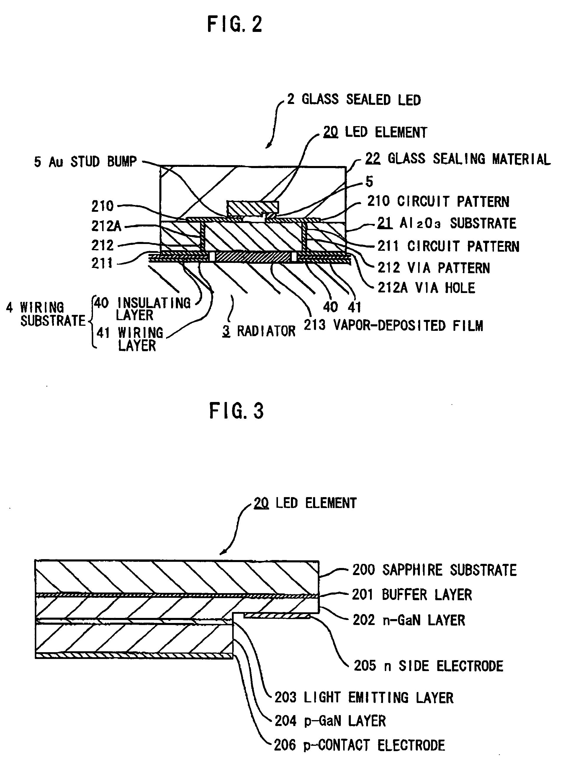
[0096]FIG. 1 is a perspective view schematically showing a light emitting device in a first preferred embodiment according to the invention and FIG. 2 is a substantial...

second embodiment

[0124] Composition of Light Emitting Device

[0125]FIG. 5 is a perspective view schematically showing a light emitting device in a second preferred embodiment according to the invention. In the following explanation, as to a part comprising same composition and function as used in the first preferred embodiment, same references are used.

[0126] The light emitting device 1 comprises a radiator with fins 30A explained in the first preferred embodiment of which edge parts are formed to a corrugated plate and compositions other than the composition of the fin 30A are same as the first preferred embodiment.

Advantages of the Second Embodiment

[0127] According to the second preferred embodiment of the invention, the edge parts of the fins 30A are formed to a corrugated plate so that a radiation area can be enlarged and a radiation performance can be enhanced. Further, plates for the fins 30A are not limited to the corrugated plate described above, but an embossed plate can be used.

third embodiment

[0128] Composition of Light Emitting Device

[0129]FIG. 6 is a perspective view schematically showing a light emitting device in the third preferred embodiment according to the invention.

[0130] The light emitting device 1 of the preferred embodiment comprises a glass sealed LED 2 mounted on a side surface of the radiator 3 so as to emit a light in a direction of X corresponding to a direction of a light axis of the LED element 20. The radiator 3 in the third preferred embodiment is formed by cutting the radiator 3 explained in the first preferred embodiment at a center part in a longitudinal direction so that a side surface composed of the cutting surface formed by the cutting of the radiator 3 constitutes a mounting surface of the glass sealed LED 2. Further, a Z direction shown in FIG. 6 represents a direction of a natural convection which generates in a vertical direction in a calm condition by that the radiation plates 30 become higher temperature than an air of circumference, o...


PUM


Abstract

A light emitting device has a light source having a light emitting element; and a radiator having plural plate members formed of a thermally-conductive material. The plural plate members are stacked on each other while allowing formation of a space between each other at an end portion thereof. The light source is mounted on a side surface of the plural stacked plate members.

Description

[0001] The present application is based on Japanese patent application Nos. 2005-316694 and 2006-281714, the entire contents of which are incorporated herein by reference. BACKGROUND OF THE INVENTION [0002] 1. Field of the Invention [0003] This invention relates to a light emitting device comprising a light emitting diode (hereinafter referred to as “LED”) element as a light source and, in particular, to a light emitting device that has a high radiation performance for heat generated from the LED element and is excellent in productivity. [0004] 2. Description of the Related Art [0005] LED is suitable for an application of a light source in view of an environmental protection and an electrical power saving. Therefore, LED is expected to be applied to a broad application such as a small sized electronics device, a lighting device and a lamp fitting as a white light source, as well as a substituting light source for a fluorescent lamp. According to this, recently, light emitting device...

Claims


Application Information

Patent Timeline
Patent Type & Authority Applications(United States)
IPC IPC(8): F21V29/00H01L33/50H01L33/62H01L33/64
CPCF21K9/00F28F3/02Y10S362/80F21V29/74F21V29/83F21V29/763F21V29/767F21V29/773F21V29/76F21Y2115/10
Inventor SUEHIRO, YOSHINOBUTASUMI, KOJI
Owner TOYODA GOSEI CO LTD
Why Eureka
Try Eureka