
Substrates and articles having selective printed surface reliefs

a printing surface and substrate technology, applied in the field of surface reliefs, can solve the problems of inability to emboss or cast in localized regions, inconvenient processes, and inability to emboss or cas

Inactive Publication Date: 2007-05-03
HOLOINKS
View PDF20 Cites 35 Cited by
  • Summary
  • Abstract
  • Description
  • Claims
  • Application Information

AI Technical Summary

Benefits of technology

[0005] It is another object of the invention to provide substrates and articles (such as currency, flexible and rigid packaging, labels, and printed forms) having selective printed surface reliefs that are applied using conventional printing equipment.
[0006] It is a further object of the invention to provide substrates and articles having printing surface reliefs that are applied at the same speeds as conventional printing processes and in substantially perfect registration to conventional printing using the same printing equipment.

Problems solved by technology

These embossing and casting processes suffer from a number of known drawbacks, including: (1) the processes are not suitable for use with the printing equipment; (2) embossing or casting in localized regions is not possible with conventional metallizing equipment; (3) the metallizing equipment is prohibitively expensive; (4) printing onto the embossed and metallized material is very slow and expensive; (5) conventional embossing and casting systems are much slower than printing equipment; (6) it is difficult to overprint onto a holographic substrate when perfect registration is required; (7) holographic substrates may cover the entire face of the substrate, which may be a problem if the final product is a label, package or security document; and (8) holographic hot-stamping and cold-stamping substrates may have to be added to the printing in attachments placed on the conventional printing equipment.

Method used


Image

  • Substrates and articles having selective printed surface reliefs
  • Substrates and articles having selective printed surface reliefs
  • Substrates and articles having selective printed surface reliefs

Examples


Embodiment Construction

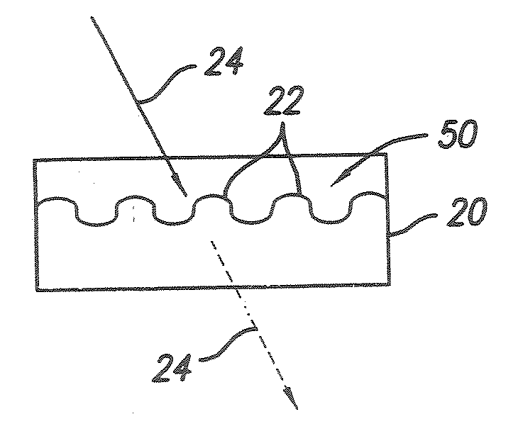
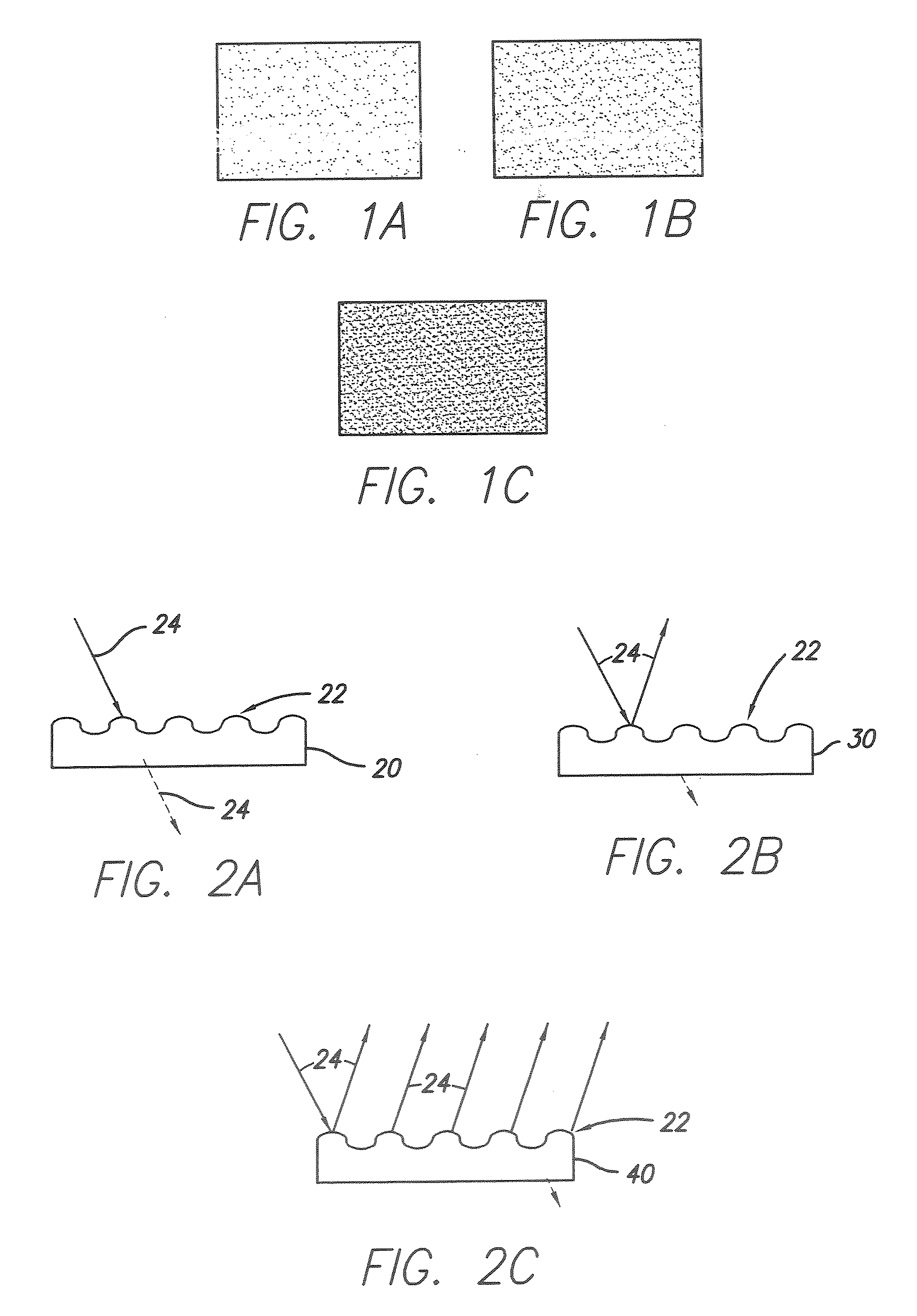
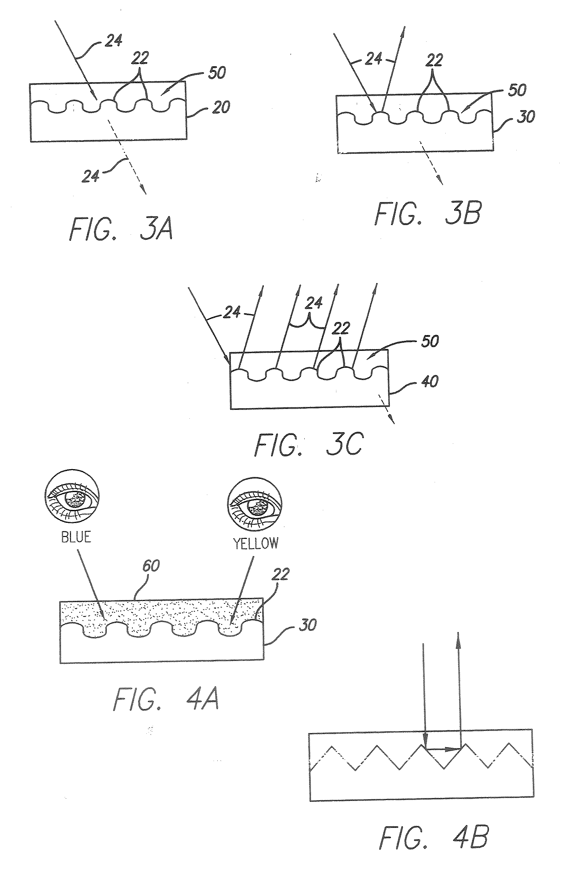
[0038] In the following paragraphs, the present invention will be described in detail by way of example with reference to the attached drawings. Throughout this description, the preferred embodiment and examples shown should be considered as exemplars, rather than as limitations on the present invention. As used herein, the “present invention” refers to any one of the embodiments of the invention described herein, and any equivalents. Furthermore, reference to various feature(s) of the “present invention” throughout this document does not mean that all claimed embodiments or methods must include the referenced feature(s).

[0039] The present invention is directed to articles that incorporate micro and nano surface reliefs such as holograms, optically variable devices, diffractions gratings, nano optical color structures, biological and animal structures, and structures that exhibit surface reliefs between about 10 nm to about 3 mm. The surface relief structures are also referred to h...


PUM


Abstract

The present invention provides articles comprising a substrate, a coating that is applied to the substrate, and surface reliefs that are cast or embossed onto the coating at substantially the same speeds and widths of conventional printing, and in substantially perfect register to conventional printing, wherein the coating is selected from the group consisting of HRISR coatings, LRISR coatings, water-based coatings, solvent-based coatings, UV / EB based coatings, sol-gel based coatings, conductive coatings, silver reduction based coatings and metallic coatings. A protective or printed layer may (or may not) be applied on top of the coating. Specifically, if the coating is an HRISR or LRISR coating, then it is unnecessary to apply a special high refractive layer because HRISR and LRISR coatings inherently contain the refractive index properties that are necessary to keep the surface reliefs viewable despite any printing on top of the coating. Otherwise, if the coating does not comprise an HRISR or LRISR coating, then a high refractive protective layer is applied on top of the coating, wherein the protective layer follows a topography of the surface reliefs such that a thickness of the protective coating is substantially uniform.

Description

REFERENCE TO RELATED APPLICATIONS [0001] This application is a Continuation-In-Part of U.S. patent application Ser. No. 11 / 198,625, filed Aug. 5, 2005, which is a Continuation-In-Part of U.S. patent application Ser. No. 11 / 144,349, filed Jun. 3, 2005, the contents of which is incorporated herein by reference in its entirety.FIELD OF THE INVENTION [0002] The present invention is directed to surface reliefs, and more particularly to, substrates and articles having selective printed surface reliefs that are applied using conventional printing equipment. BACKGROUND OF THE INVENTION [0003] Conventional holographic surface reliefs are manufactured by slow embossing and casting processes that are separate from mainstream printing processes. For example, the processes may involve embossing onto pre-metallized materials or casting onto clear films and papers, and then metallizing the embossed materials. These embossing and casting processes suffer from a number of known drawbacks, including:...

Claims


Application Information

Patent Timeline
IPC IPC(8): B32B3/00
CPCB41F5/22B41F13/22B41F31/002Y10T428/24612B41P2213/734B42D25/328B41P2200/12
Inventor LIEBERMAN, DANIEL
Owner HOLOINKS
Learn More