Connector

a technology of connecting rods and connectors, applied in the direction of connection, electrical apparatus, coupling device connection, etc., can solve the problems of increasing the production cost of connectors, unable to achieve proper transmission, and difficult to obtain impedance matching, etc., and achieves the effect of easy matching

Inactive Publication Date: 2007-05-03
YAZAKI CORP
View PDF6 Cites 23 Cited by
  • Summary
  • Abstract
  • Description
  • Claims
  • Application Information

AI Technical Summary

Benefits of technology

[0030] In the present invention, there can be provided the connector in which the impedance of the connector can be easily matched with the impedance of the cable without depending on the synthetic resin for forming the connector housing.

Problems solved by technology

If impedance mismatch is encountered, reflection of the signal occurs at such a mismatching region, so that the proper transmission can not be effected.
However, when a different synthetic resin is used for each connector, it is feared that the production cost of the connector increases.
Furthermore, when connectors become increasingly compact in design, it is thought that it is difficult to obtain impedance match even with the use of teflon, and besides teflon is relatively expensive.
Therefore, even when the connector housing-forming synthetic resin is suitably changed, this synthetic resin is limited to a special one having excellent heat resistance and a low dielectric constant.

Method used


Image

  • Connector
  • Connector
  • Connector

Examples


first embodiment

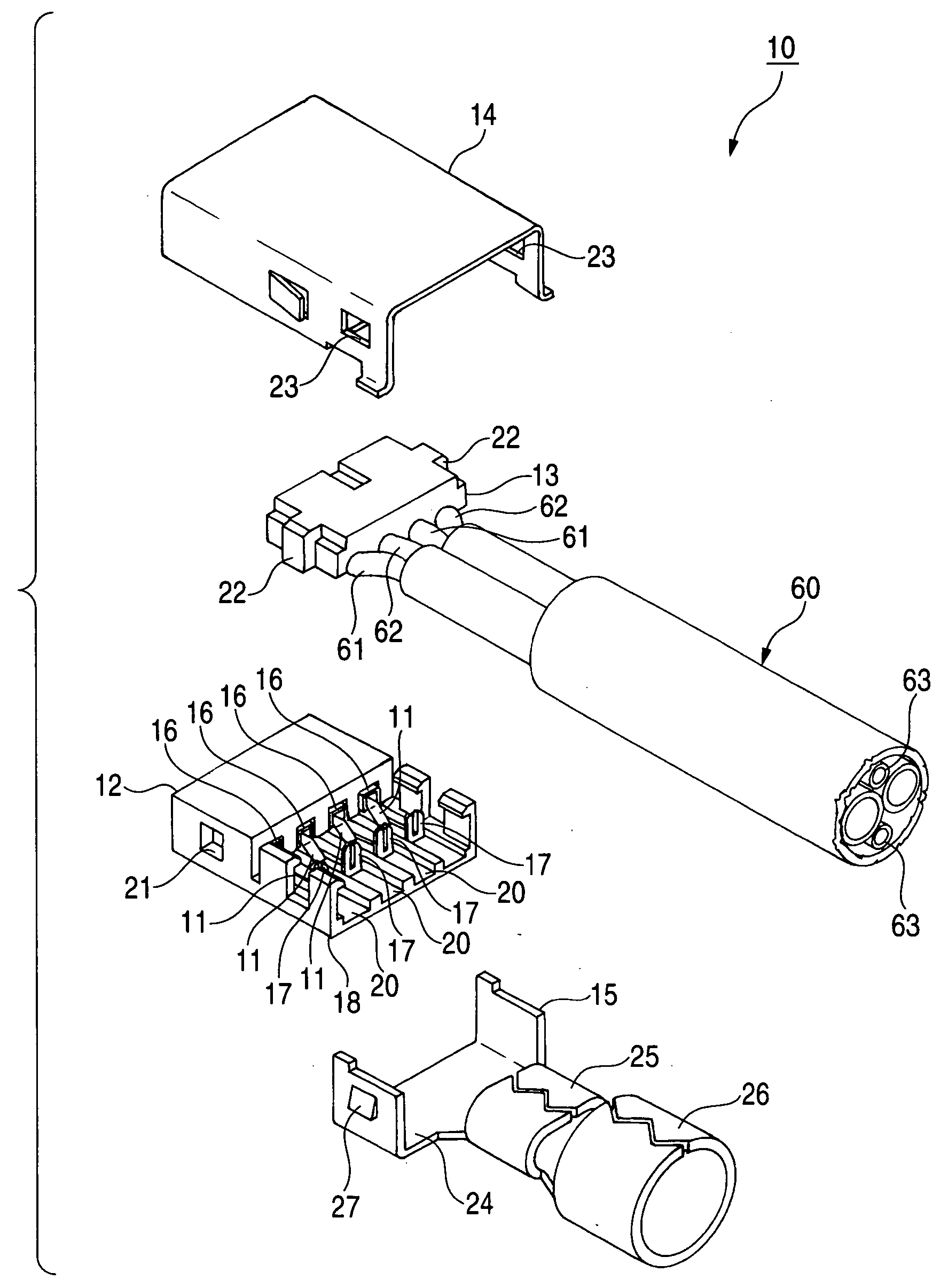
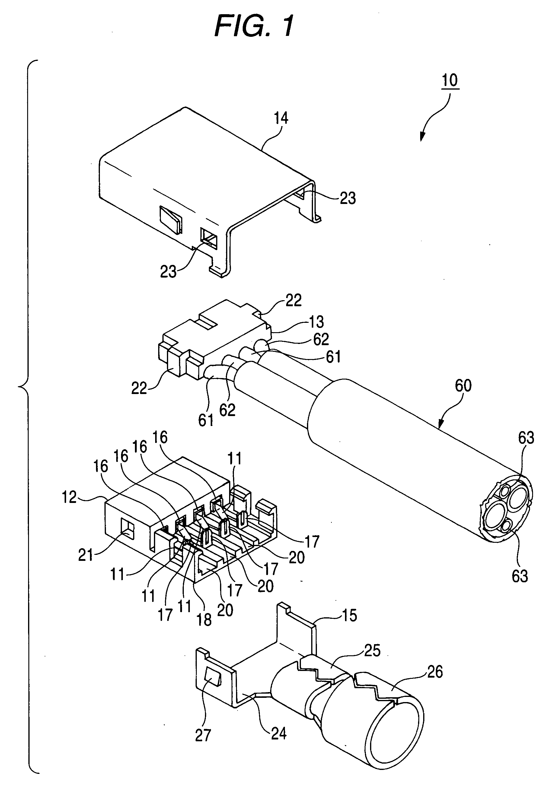
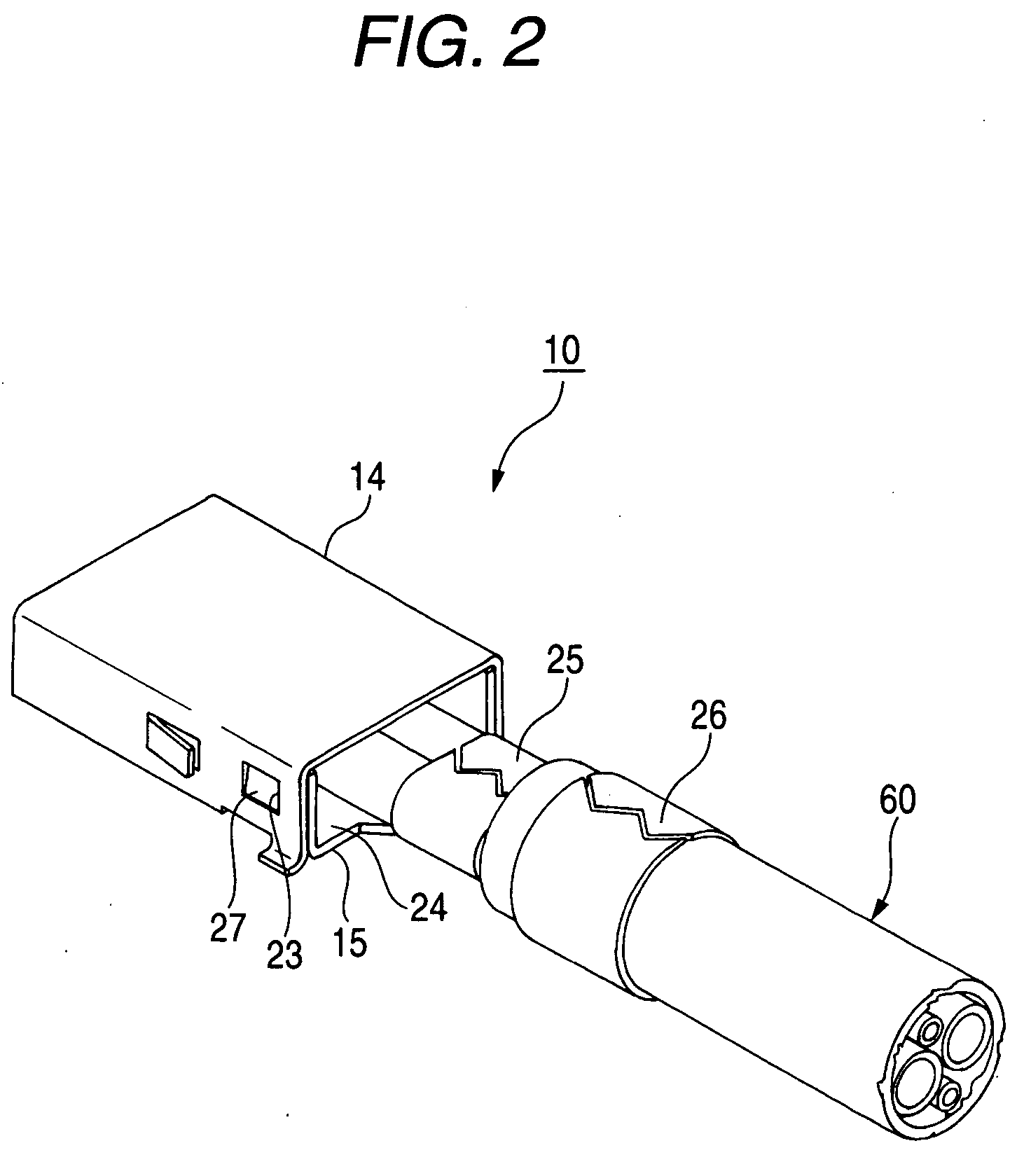
[0042]FIG. 1 is an exploded, perspective view of a first embodiment of a connector of the invention, FIG. 2 is a perspective view showing the connector of FIG. 1 in its assembled condition, FIG. 3 is a partially-broken, perspective view of a connector housing of the connector of FIG. 1, and FIG. 4 is a cross-sectional view of the connector housing taken along the line IV-IV of FIG. 3.

[0043] As shown in FIGS. 1 and 2, the connector 10 of this embodiment is used in the above-mentioned differential-type transmission, and is secured to a distal end of a cable 60. In the following description, the direction of connecting of the connector 10 to a mating connector attached to an electronic equipment or the like will be defined as “forward direction”.

[0044] The cable 60 has two signal paths each including two signal wires 61 and 62, and a grounding wire 63. Voltages of the two signal wires 61 and 62 are equal in magnitude to each other, and are 180° out of phase with each other, and a vol...

second embodiment

[0059] Next, a second embodiment of a connector of the invention will be described with reference to FIGS. 5 and 6. FIG. 5 is a partially-broken perspective view of a connector housing used in the connector of the second embodiment, and FIG. 6 is a cross-sectional view of the connector housing taken along the line VI-VI of FIG. 5.

[0060] The connector of this embodiment differs from the above-mentioned connector 10 of the first embodiment only in a front end portion of a connector housing 12 having terminal receiving chambers 19, and therefore any figure, showing the overall construction of the connector of this embodiment, is not provided here, and those constituent elements identical or similar in function to those of the above connector 10 will be designated by identical or like reference numerals, respectively, and explanation thereof will be simplified or omitted.

[0061] As shown in FIG. 5, in the connector 30 of this embodiment, instead of the wall reduction portions 21 formed...


PUM


Abstract

A connector includes a connector housing having a plurality of terminal receiving chambers arranged in a row, and a plurality of terminals which are connected respectively to end portions of a plurality of wires of a cable, and are received respectively in the terminal receiving chambers. Wall reduction portions are formed respectively in partition walls of the connector housing, each interposed between the adjacent terminal receiving chambers, so that an impedance of the connector can be matched with an impedance of the cable.

Description

BACKGROUND OF THE INVENTION [0001] 1. Field of the Invention [0002] This invention relates to a connector secured, for example, to a cable installed in a vehicle such as an automobile. [0003] 2. Related Art [0004] Various electronic equipments such for example as a navigation system are mounted on a vehicle such as an automobile. Cables each comprising a plurality of wires are installed in the vehicle so as to supply electric power to these electronic equipments and also to transmit signals between the electronic equipments. A connector for connection to a connector of the electronic equipment is secured to the cable. [0005] For example, the above navigation system comprises a body portion for calculating a present position of the vehicle, and a display for indicating the present position of the vehicle and the position of a destination, and the body portion and the display are connected together via a cable. In recent years, the display has been required to have high resolution, an...

Claims


Application Information

Patent Timeline
Patent Type & Authority Applications(United States)
IPC IPC(8): H01R12/24
CPCH01R4/185H01R4/2433H01R9/035H01R13/506H01R13/6471H01R13/6477H01R13/6581H01R13/65915
Inventor KAMEYAMA, ISAO
Owner YAZAKI CORP
Why Eureka
Try Eureka