Mobile robot

a mobile robot and robot technology, applied in the direction of process and machine control, distance measurement, instruments, etc., can solve the problem of troublesome operation for users

Active Publication Date: 2007-05-03
HITACHI LTD
View PDF9 Cites 148 Cited by
  • Summary
  • Abstract
  • Description
  • Claims
  • Application Information

AI Technical Summary

Benefits of technology

[0004] In the first nonpatent literature, or “Multimodal User Interface for Mobile Robots,” it is necessary to precisely set the path not to collide with obstacles. In the second nonpatent literature, or “A method of Off-Line Teaching for Corridor Environment with Freehand Maps,” it is necessary to set the markers although a precise path is not necessary. Thus, in the conventional techniques, it is necessary to previously set the details of information of the environment in which the robot exists, and hence such operations are troublesome for the user.

Problems solved by technology

Thus, in the conventional techniques, it is necessary to previously set the details of information of the environment in which the robot exists, and hence such operations are troublesome for the user.

Method used


Image

  • Mobile robot
  • Mobile robot
  • Mobile robot

Examples


embodiment 1

[0017] An embodiment of the invention will be described with reference to the accompanying drawings.

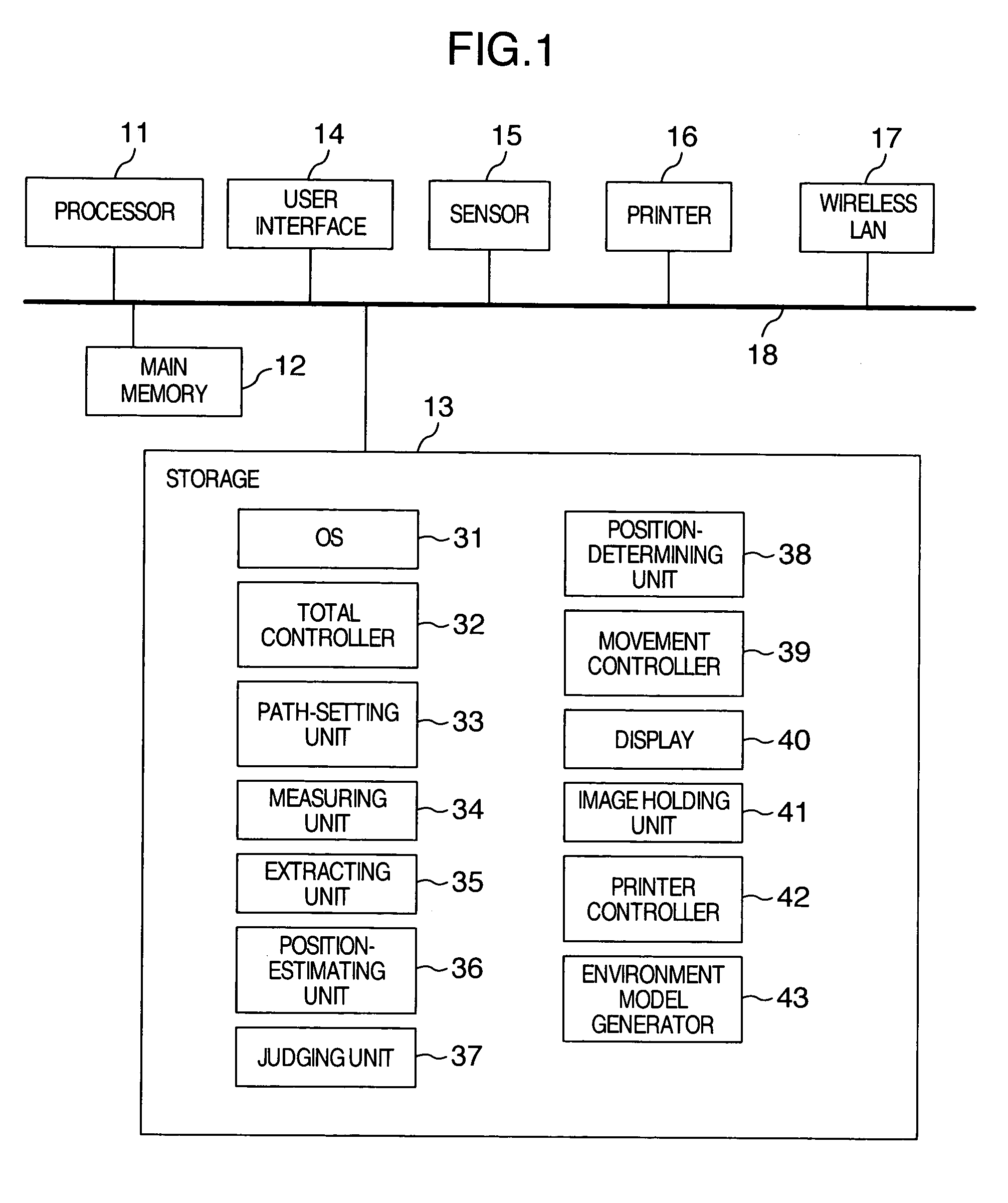
[0018]FIG. 1 is a diagram showing the hardware construction of a system of this embodiment.

[0019] This system has a processor 11 for the processing based on a program, a main memory 12 for temporarily storing data, a storage 13, a user interface (display, graphic board, mouse, robot control board, range finder control board and so on) 14, a sensor 15, a printer 16, a wireless LAN 17 and a connection line 18 for connecting these units.

[0020] The robot treated in this invention may be any mobile apparatus. For example, the system itself shown in FIG. 1 may be used as a robot or a carriage that carries this system may be used as a robot. In addition, the shape of the robot may be an arbitrary type such as vehicle type, vessel type or leg type.

[0021] The storage 13 includes programs for the functions of an OS 31, a total controller 32 for controlling the whole processing, a path setti...

embodiment 2

[0041] The embodiment 2 is a robot with a printer mounted.

[0042] The user is able to set the path of the robot by using the wireless LAN 17 and the user interface such as a remote PC without limiting to the user interface mounted on the robot. This function can be achieved by the equipment for the remote desktop technology that enables the image to be displayed on a remote PC or by the equipment that enables GUI to be operated on the home page (hereinafter, referred to as HP) from a remote PC.

[0043] For example, it is assumed to previously create paths of the robot between the seats of a plurality of users who work in an office. At this time, when a certain user orders a printout through the wireless LAN, the printer controller 42 starts printing-out operation. As the printing-out operation goes on, the robot starts to move from the current position to the seat of the user who ordered the printout. Thus, the printing-out operation can be carried out in parallel with the movement o...

embodiment 3

[0045] The third embodiment 3 concerns a system that displays collected environmental information for remote users.

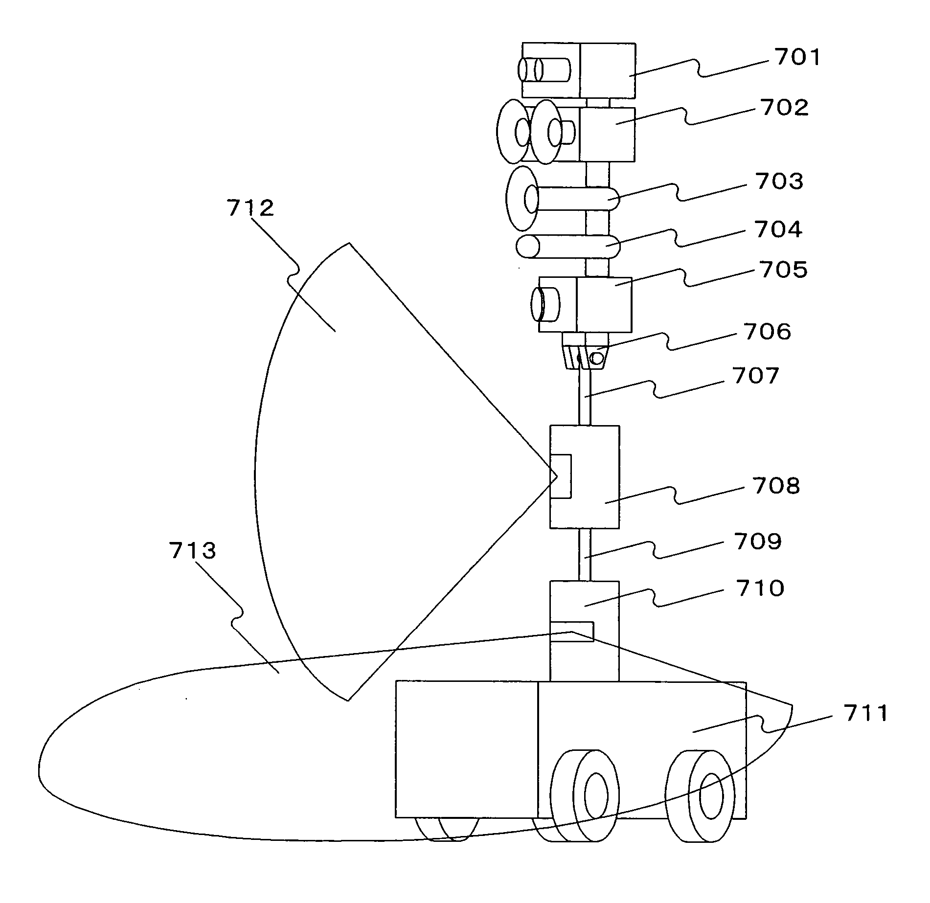
[0046]FIG. 7 shows the appearance of the robot. On a carriage 711 are mounted a camera 705, laser range finders 708 and 710, an infrared sensor 701, an ultrasonic sensor 702, a microphone 704 and a loud speaker 703. These devices can be adjusted in their pan / tilt and height by a universal head assembly 706, 707, 709. In addition, the laser range finder 708 measures the geometrical shape of an obstacle as viewed in the vertical direction by using a vertically scanning laser 712. The laser range finder 710 measures the geometrical shape of an obstacle as viewed in the horizontal direction by using a horizontally scanning laser 713.

[0047] This robot is placed in an office or factory, and the user gives a rough path to the robot. This path may be given on the PC screen mounted on the robot or on a remote PC screen. The measuring unit 44 controls the laser range finders 70...


PUM


Abstract

The system constructs a robot autonomously move by simply inputting a rough path. The system has a path-setting unit for setting the path of a mobile apparatus according to the inputted path, a measuring unit for measuring an environment in which the mobile apparatus exists, an extracting unit for extracting an object existence region in the environment according to the values measured by the measuring unit, a judging unit that judges the validity of the path according to the path set by the path setting unit and to the object existence region extracted by the extracting unit, a position determining unit that determines a target position to which the mobile apparatus is to move by selecting it from the portions of the path judged as valid, and a movement controller for controlling the mobile apparatus to move to the target position.

Description

INCORPORATION BY REFERENCE [0001] The present application claims priority from Japanese application JP 2005-312141 filed on Oct. 27, 2005, the content of which is hereby incorporated by reference into this application. BACKGROUND OF THE INVENTION [0002] The present invention relates to autonomous mobile robots. [0003] A technique for autonomous mobile a robot is proposed in which an user previously draws a path of the robot on a PC screen not to collide with obstacles (see, Myers G., Julia L. Cheyera, and Gherbi S., “Multimodal User Interface for Mobile Robots,” Eleventh Annual Symposium on User Interface Software and Technology, 1998). In addition, there is another technique in which the user previously draws a brief path of the robot on a PC screen and sets on the PC screen the markers of intersections, T-shaped cross points and so on existing in the actual environment (see, Kazumi Oikawa, Takeshi Tsuchiya, “A Method of Off-Line Teaching for Corridor Environment with Freehand Maps...

Claims


Application Information

Patent Timeline
Patent Type & Authority Applications(United States)
IPC IPC(8): G06F19/00G05D1/02
CPCG05D1/024G05D1/0242G05D1/0255G05D1/0274G05D2201/0211G06N3/008
Inventor MATSUMOTO, KOSEIMORIYA, TOSHIOYANO, KAZUO
Owner HITACHI LTD
Why Eureka
Try Eureka