Hybrid vehicle drive control system

a technology of drive control system and hybrid vehicle, which is applied in the direction of fluid gearing, machine/engine, process and machine control, etc., can solve the problems of generating shock, passengers and drivers in particular, and causing unpleasant sensation, so as to prevent the incidence of engine starting shock and the lack of torque transfer capacity.

Active Publication Date: 2007-05-10
NISSAN MOTOR CO LTD
View PDF12 Cites 81 Cited by
  • Summary
  • Abstract
  • Description
  • Claims
  • Application Information

AI Technical Summary

Benefits of technology

[0008] The present invention was conceived in view of the abovementioned problem. One object of the present invention is to provide a hybrid vehicle drive control system for a hybrid vehicle in which a lack of torque transfer capacity can be prevented from occurring whether the engine of an electric vehicle has been started or is being started while in electric automobile running mode, the possibility of the engine stalling or juddering is eliminated, and the incidence of engine starting shock can be prevented.

Problems solved by technology

Therefore, the variations in the engine output torque generated in the period between cranking and the initial combustion is transmitted directly to the transmission output axle, which often generates a shock.
In such instances, the passengers and the driver in particular will be subjected to an unpleasant sensation because of this shock, which unexpectedly occurs while the vehicle is moving.

Method used


Image

  • Hybrid vehicle drive control system
  • Hybrid vehicle drive control system
  • Hybrid vehicle drive control system

Examples


Embodiment Construction

[0024] Selected embodiments of the present invention will now be explained with reference to the drawings. It will be apparent to those skilled in the art from this disclosure that the following descriptions of the embodiments of the present invention are provided for illustration only and not for the purpose of limiting the invention as defined by the appended claims and their equivalents.

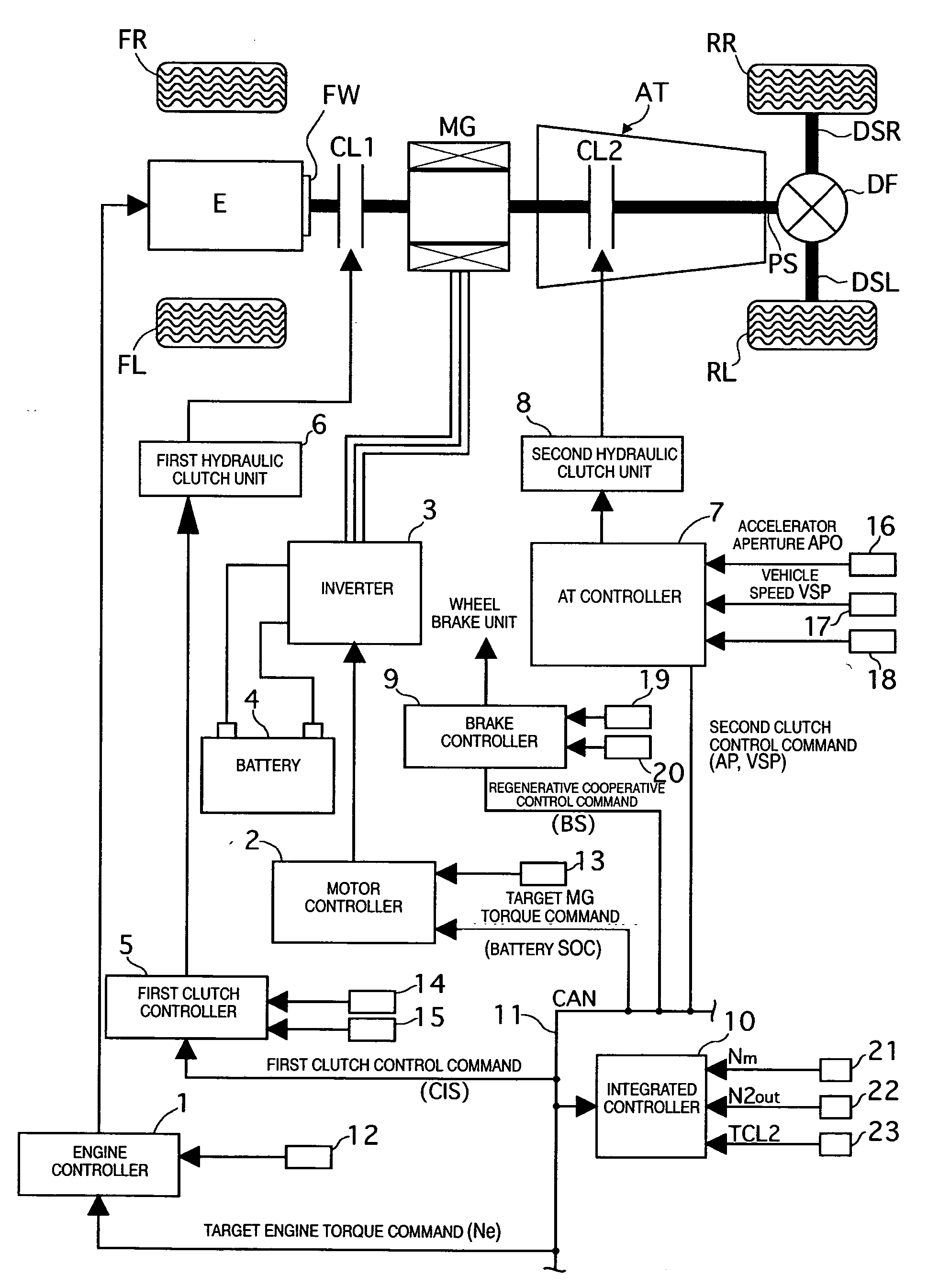
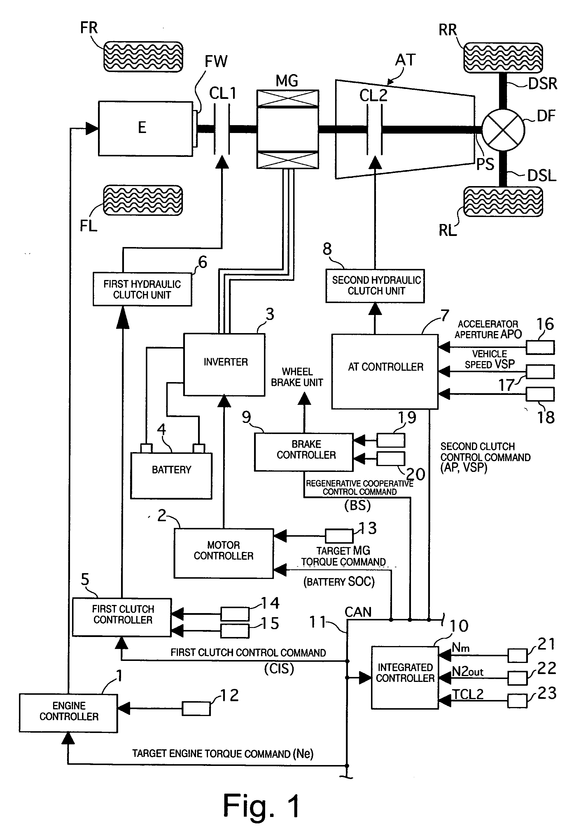
[0025] Referring initially to FIG. 1, a power train of a rear-wheel drive hybrid vehicle is schematically illustrated with a hybrid vehicle drive control system in accordance with a first embodiment of the present invention. As shown in FIG. 1, the hybrid vehicle drive control system of the first embodiment basically includes an internal combustion engine E, a flywheel FW, a first clutch CL1, a motor / generator MG, a second clutch CL2, an automatic transmission AT (gearbox), a propeller shaft PS, a differential gear unit DF, a left drive shaft DSL, a right drive shaft DSR, a left rear wheel RL (dr...


PUM


Abstract

A hybrid vehicle drive control system has a first clutch interposed between an engine and a motor/generator, a transmission including several gear position clutches arranged between the motor/generator and a drive wheel, and a controller. The controller selectively starts the engine using torque from the first clutch during a mode drive change from an electric drive mode to a hybrid drive mode. When an engine start command occurs during the drive mode change, the controller selects the engaged gear position clutch that has the maximum torque transfer capacity from the engaged clutches constituting a vehicle running gear occurring during an engine starting process as a second clutch to be controlled. Then the controller executes a slip control of the second clutch when the first clutch is being connected to start the engine during the mode change from the electric drive mode to the hybrid drive mode.

Description

CROSS-REFERENCE TO RELATED APPLICATIONS [0001] This application claims priority under 35 U.S.C. § 119 to Japanese Patent Application No. 2005-324295 filed on Nov. 9, 2005. The entire disclosure of Japanese Patent Application No. 2005-324295 is hereby incorporated herein by reference. BACKGROUND OF THE INVENTION [0002] 1 Field of the Invention [0003] The present invention relates to a hybrid vehicle drive control system of a hybrid vehicle having an electric drive (EV) mode a hybrid drive (HEV) mode. More particularly, the present invention relates to a hybrid vehicle drive control system for starting an engine of a hybrid vehicle having a first clutch is interposed between the engine and a motor / generator, and a second clutch is interposed between the motor / generator and a drive wheel, with one of a plurality of clutches disposed within a transmission being used as the second clutch. [0004] 2. Background Information [0005] Various configurations have been proposed for hybrid vehicle...

Claims


Application Information

Patent Timeline
Patent Type & Authority Applications(United States)
IPC IPC(8): B60K1/00B60K6/48B60K6/547B60L50/16B60W10/02B60W10/06B60W10/08B60W10/10B60W20/00F02D29/00F02D29/02F02D29/06F02N11/04F02N15/02F16D48/02F16H59/18F16H59/68F16H59/74F16H61/02F16H61/68F16H61/684F16H61/686F16H63/40F16H63/50
CPCB60K6/48B60K6/547B60W10/02B60W10/06B60W10/115Y10T477/26B60W2540/10B60W2710/025Y02T10/6221Y10S903/912B60W20/00B60L15/2054B60L2240/12B60L2240/14B60L2240/423B60L2240/443B60L2240/507B60L50/16Y02T10/62Y02T10/64Y02T10/7072Y02T10/72B60K6/08F16H61/00F16H47/00B60W20/40B60W20/10Y02T10/70
Inventor NOZAKI, YUJINAKAMURA, KIMINORI
Owner NISSAN MOTOR CO LTD
Why Eureka
Try Eureka