Torch hex end structure

a technology of hex end and torch, which is applied in the field of torch, can solve the problems of substantial deterioration of the forward end of the torch including the contact tip and diffuser, adversely affecting the operability of the torch during the welding operation, and substantial increase in the cos

Inactive Publication Date: 2007-05-10
LINCOLN GLOBAL INC
View PDF18 Cites 7 Cited by
  • Summary
  • Abstract
  • Description
  • Claims
  • Application Information

AI Technical Summary

Benefits of technology

[0015] One advantage of the present invention is the provision of mounting a conduit to a housing of the welding gun in several positions without completely disassembling the gun.
[0016] Another advantage of the present invention is the provision of mounting the gun to a remote arm in one of several positions without completely disassembling the gun.
[0017] Yet another advantage of the present invention is the provision of providing a shielding gas through the housing to the conduit.
[0018] Another advantage of the present invention is the provision of providing anti-spatter liquid or an air purge to the welding gun.
[0019] Still other advantages and aspects of the invention will become apparent through the following description and the accompanying drawings.

Problems solved by technology

All of these requirements of a torch require complex machined components at the end of the torch which substantially increases the cost and adversely affects the operability of the torch during the welding operation.
Furthermore, the welding operation itself creates spatter, especially during short circuit conditions so the forward end of the torch including the contact tip and diffuser is subject to substantial deterioration over time caused by spatter together with the tremendous arc temperature involved in the welding operation.
Such closeness drastically increases the tendency for spatter to affect the laminar flow of shielding gas from the diffuser orifices.
Previously, when robotic gun assemblies were dismantled, the down time was extensive because there was no quick and easy means to precisely reassemble the robotic gun.

Method used


Image

  • Torch hex end structure
  • Torch hex end structure
  • Torch hex end structure

Examples


Embodiment Construction

[0040] The apparatus shown in the accompanying drawings and described below are examples which embody the invention. It should be noted that the scope of the invention is defined by the accompanying claims, and not necessarily by specific features of exemplary embodiments.

[0041] For a welding operation of the type which the invention is concerned, it is the usual practice to provide a service station. This service station provides: a welding current of electricity; anti-oxidizing gas; a motor for feeding welding wire to the weld; and, optionally, a vacuum source for extracting fumes.

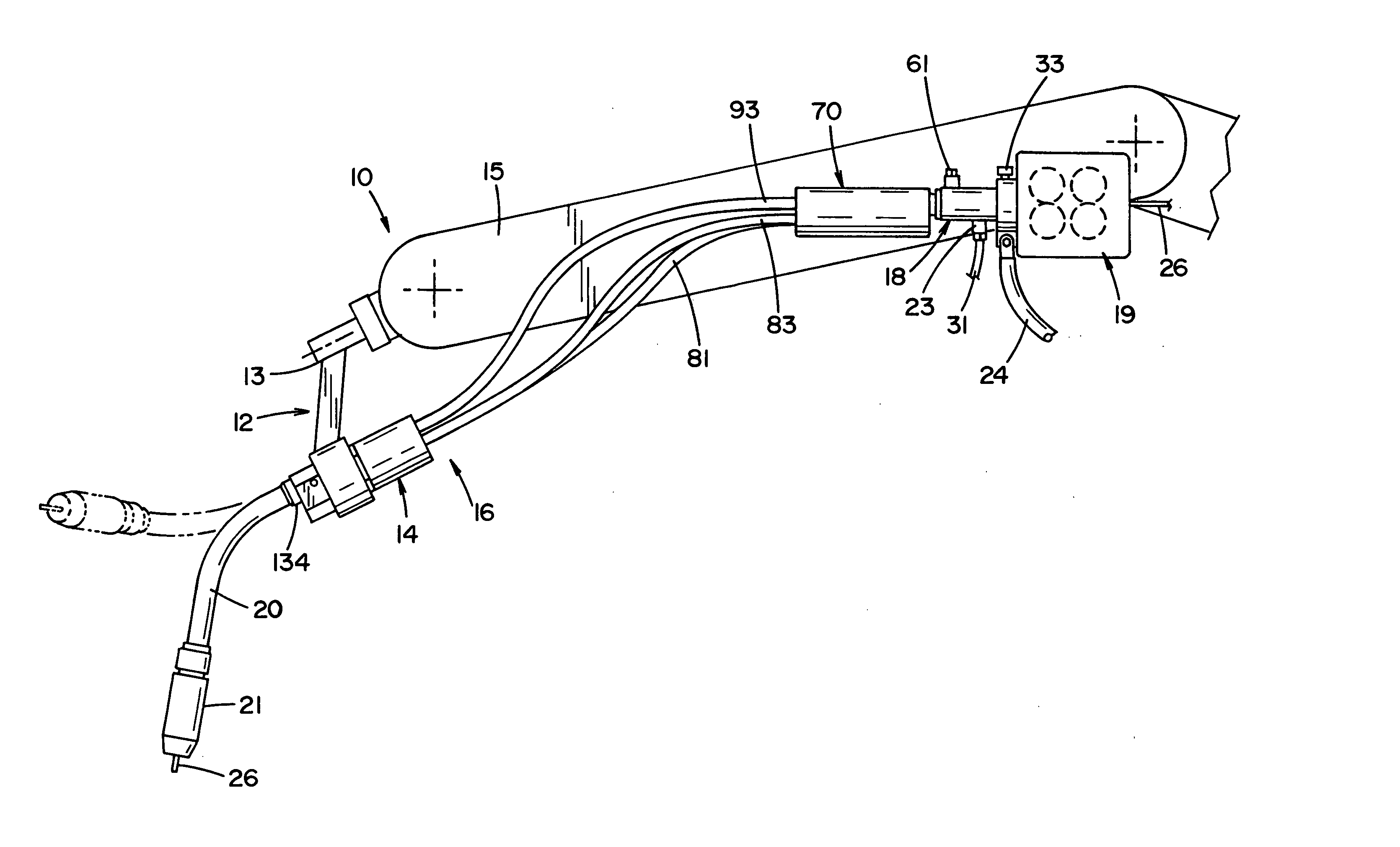
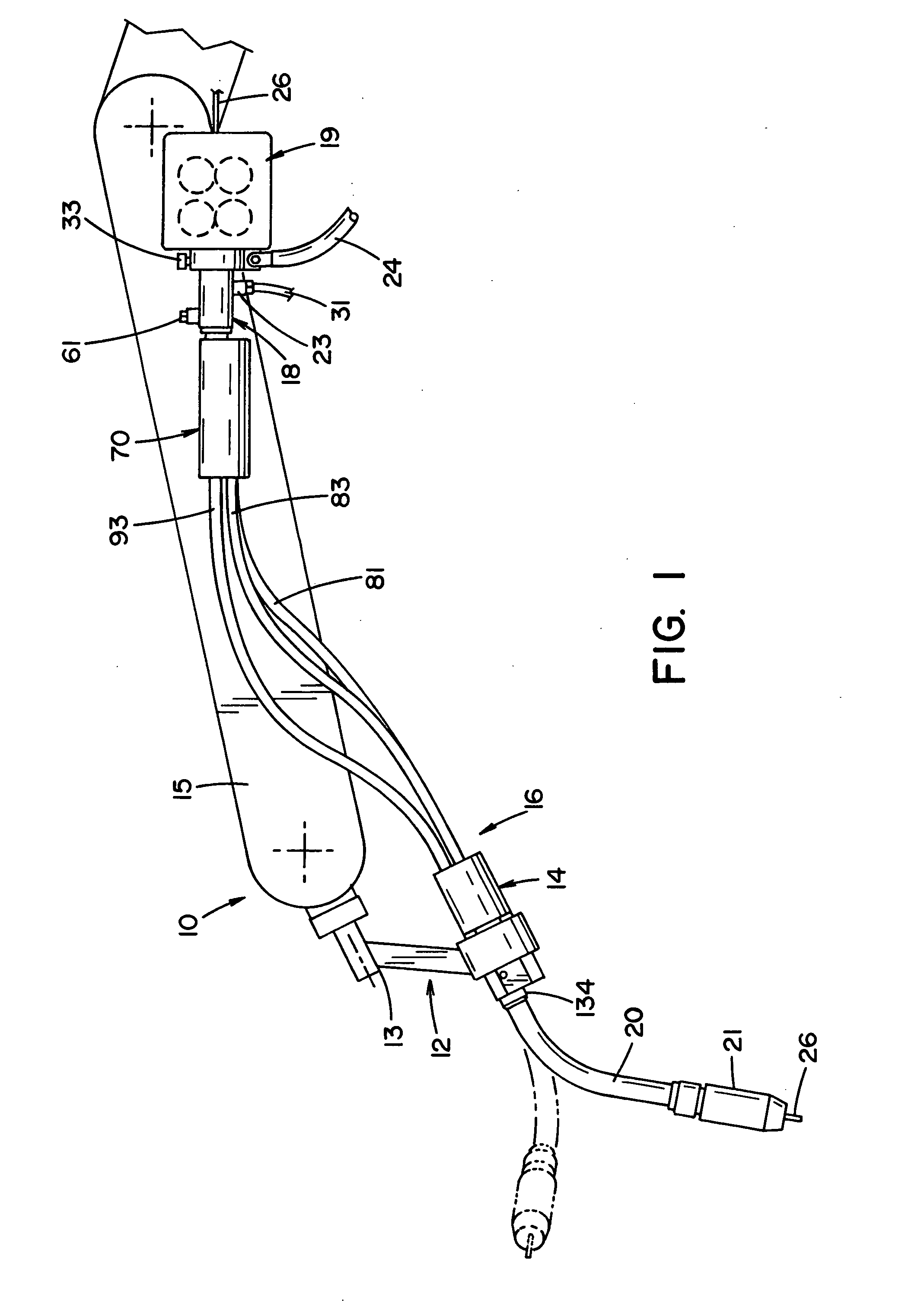
[0042] Referring now to FIG. 1, a robotic arm assembly generally designated by the numeral 10 includes a welding gun mount arm 12, a welding gun front or first housing 14 and a welding gun assembly 16. The gun mount arm 12 is a precision made instrument, typically manufactured from an aluminum alloy, preferably from 6061 aluminum alloy or the like. The gun mount arm 12 of the preferred embodiment is ro...


PUM

PropertyMeasurementUnit
flexibleaaaaaaaaaa
conductiveaaaaaaaaaa
poweraaaaaaaaaa

Abstract

A welding gun assembly for directing a welding wire toward a workpiece, having a torch at a forward portion of the gun; a welding wire feeder at a rearward portion of the gun; a first housing positioned adjacent the torch; and a second housing positioned adjacent the wire feeder. The second housing has a hexagonally shaped opening for receiving a conduit having a hexagonal portion. The conduit is positioned in one of six positions in the housing. The first housing has a hexagonal shape for being mounted to a hexagonal opening of a remote arm. A block having a hexagonal shape is received within a hexagonal opening of the housing. A hexagonal conduit is received within the block and secured in one of six positions.

Description

BACKGROUND [0001] The invention relates to the art of electric arc welding and more particularly to an improved torch for the gun between a wire feeder and the welding operation. INCORPORATION BY REFERENCE [0002] The design of the torch at the welding end of a gun is the subject of many patents that describe the background of the present invention. Some of these patents and / or applications are United Kingdom Application No. 2,285,404; Canadian Application No. 2,106,837; Canadian Application No. 2,139,152; European Application No. 0 590 728 A1; and U.S. Pat. No. 5,313,046. These prior art examples of the torch to which the present invention is directed are incorporated by reference herein as background information and to describe some of the attributes required for a torch of the type to which the invention is directed. BACKGROUND OF THE INVENTION [0003] In electric arc welding, a gun is a flexible, elongated element having a rear end connected to a wire feeder and a front end for a ...

Claims


Application Information

Patent Timeline
Patent Type & Authority Applications(United States)
IPC IPC(8): B23K9/12
CPCB23K9/295
Inventor ZAMUNER, FRANK
Owner LINCOLN GLOBAL INC
Why Eureka
Try Eureka