Aircraft attitude control configuration

Active Publication Date: 2007-05-10
MORGAN AIRCRAFT LLC
View PDF41 Cites 44 Cited by
  • Summary
  • Abstract
  • Description
  • Claims
  • Application Information

AI Technical Summary

Benefits of technology

[0005] An aircraft attitude control configuration enables control surfaces to provide attitude control for an aircraft at hover or low air speed conditions. The aircraft attitude control configuration includes a thruster mounted to an aircraft for thrusting air, a first control surface kinematically coupled to the aircraft at a position downstream of the thruster, and a second control surface kinematically coupled to the aircraft at a position downstream of the thruster, the second control surface being differentially movable with respect to the first control surface such that a portion of the thrusted air from the thruster generates a first vector force on the first control surface and another portion of the thrusted air generates a second vector force on the second control surface, so that the first and the second vector forces, provide a net roll component about the Y-Roll axis.
[0006] In another embodiment, the aircraft includes multiple thrusters for maintaining attitude control. This aircraft configuration includes a plurality of thrusters mounted to an aircraft for thrusting air, a first control surface kinematically coupled to the aircraft at a position downstream of a first thruster such

Problems solved by technology

The costs of these materials significantly add to the expense of an aircraft's manufacture.
Additionally, operating a control surface in the hot air plume of a thrus

Method used


Image

  • Aircraft attitude control configuration
  • Aircraft attitude control configuration
  • Aircraft attitude control configuration

Examples


Embodiment Construction

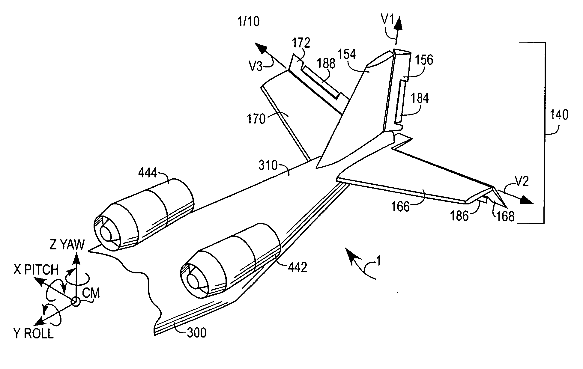
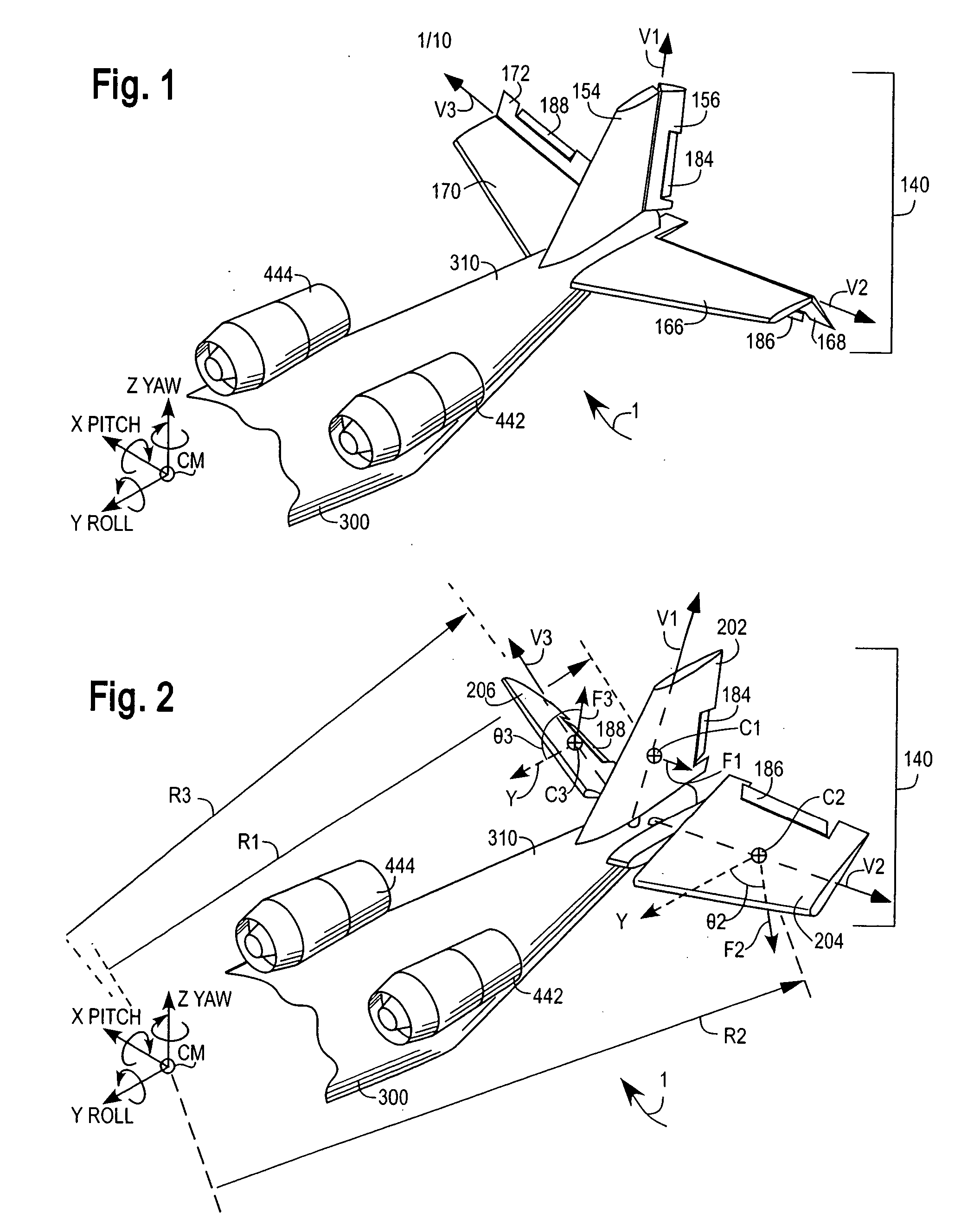
[0055] With reference to FIG. 1, one embodiment of the invention comprises an airplane or aircraft 1 with a fuselage 300 having a tail boom 310 to which is mounted an empennage or tail assembly 140. The empennage 140 preferably comprises multiple kinematically coupled control surfaces mounted in the fluid flow thrust stream or thrust plume in the streamline flow downstream from at least one upstream fluid thruster 442 mounted on the aircraft. The propulsive fluid thruster 442 is typically driven by an internal combustion or jet prime mover. A left roll-pitch elevator 168 is preferably kinematically (pivotably or otherwise movably) coupled on a left horizontal stabilizer 166 mounted to the tail boom 310. A right roll-pitch elevator 172 is preferably kinematically mounted on a right horizontal stabilizer 170 attached to the tail boom 310, such as with pivoting supports. These elevators 168 and 172 are typically complemented by a Yaw control surface or rudder 156 kinematically coupled ...


PUM


Abstract

An aircraft attitude control configuration enables control surfaces to provide attitude control for an aircraft at hover or low air speed conditions. The aircraft attitude control configuration includes a thruster mounted to an aircraft for thrusting air, a first control surface kinematically coupled to the aircraft at a position downstream of the thruster, and a second control surface kinematically coupled to the aircraft at a position downstream of the thruster, the second control surface being differentially movable with respect to the first control surface such that a portion of the thrusted air from the thruster generates a first vector force on the first control surface and another portion of the thrusted air generates a second vector force on the second control surface, so that the first and the second vector forces provide a net roll moment about the Y-Roll axis.

Description

[0001] This application claims priority from U.S. provisional patent application bearing Ser. No. 60 / 734,950, which is entitled “Empennage Control” and was filed on Nov. 9, 2005.FIELD OF INVENTION [0002] The present invention relates to control of a powered aircraft, and more specifically to control of an aircraft in hover or slow relative wind movement. BACKGROUND [0003] The attitude or vector spatial orientation of an aircraft is typically controlled using a plurality of fluid diverting control surfaces. Air flowing over or against these control surfaces during flight generates fluid forces on those surfaces. These forces and their corresponding moments about the aircraft's center of mass help control the aircraft's attitude. Most aircraft experience low fluid forces on their control surfaces in Vertical Take Off and Landing aircraft, Short Take Off and Landing, and / or Short / Vertical Takeoff and Landing aircraft (VTOL, STOL and / or S / VTOL) typically do not experience strong fluid f...

Claims


Application Information

Patent Timeline
IPC IPC(8): B64C9/06
CPCB64C5/02B64C5/06B64C9/06B64C9/12Y02T50/32Y02T50/30
Inventor MORGAN, BRIAN HERMANHAGEN, DAVID LEROY
Owner MORGAN AIRCRAFT LLC
Why Eureka
Try Eureka