Eureka AIR delivers breakthrough ideas for toughest innovation challenges, trusted by R&D personnel around the world.

Operational amplifier

Active Publication Date: 2007-05-10
AVAGO TECH INT SALES PTE LTD
View PDF5 Cites 3 Cited by
  • Summary
  • Abstract
  • Description
  • Claims
  • Application Information

AI Technical Summary

Benefits of technology

[0006] According to one embodiment of the present invention, a high linearity, high drivability four-stage operational amplifier is described. The operational amplifier includes a first stage, a second stage, a third stage, and a fourth stage. The amplifier includes a nested transconductance-capacitance compensation configuration. The third stage includes class AB control mechanism. The fourth stage includes a class AB output stage.

Problems solved by technology

In this environment, ordinary operational amplifiers are insufficient because prior art amplifiers do not provide sufficient drive current.
Unfortunately, if a heavy resistive load is applied to this amplifier, the output stage current will be insufficient to drive the load unless the biasing current of the output stage is set at an unreasonable level.
For example, prior art operational amplifiers that use a class A output is not suitable for driving the type of resistive load encountered in power line communication systems.
Furthermore, in the design of multi-stage operational amplifiers instability and signal distortion are always of concern to the designer.
In power line communication systems, stability issues are of even greater concern because the power line impedance changes with time and can become very low sometimes. Prior art operation amplifiers often exhibit an undesirable AC response, which can cause the amplifier to become unstable during operation.
Large signal distortion is undesirable because the distortion prohibits the effective and efficient transmission of signals.
Unfortunately, the implementation has large distortions due to its unbalanced gains in the PMOS path and the NMOS path.

Method used


Image

  • Operational amplifier
  • Operational amplifier
  • Operational amplifier

Examples


Embodiment Construction

[0012] An operational amplifier with improved stability and drive capability is described. In the following description, for the purposes of explanation, numerous specific details are set forth in order to provide a thorough understanding of the present invention. It will be apparent, however, to one skilled in the art that the present invention may be practiced without these specific details. In other instances, well-known structures and devices are shown in block diagram form in order to avoid unnecessarily obscuring the present invention.

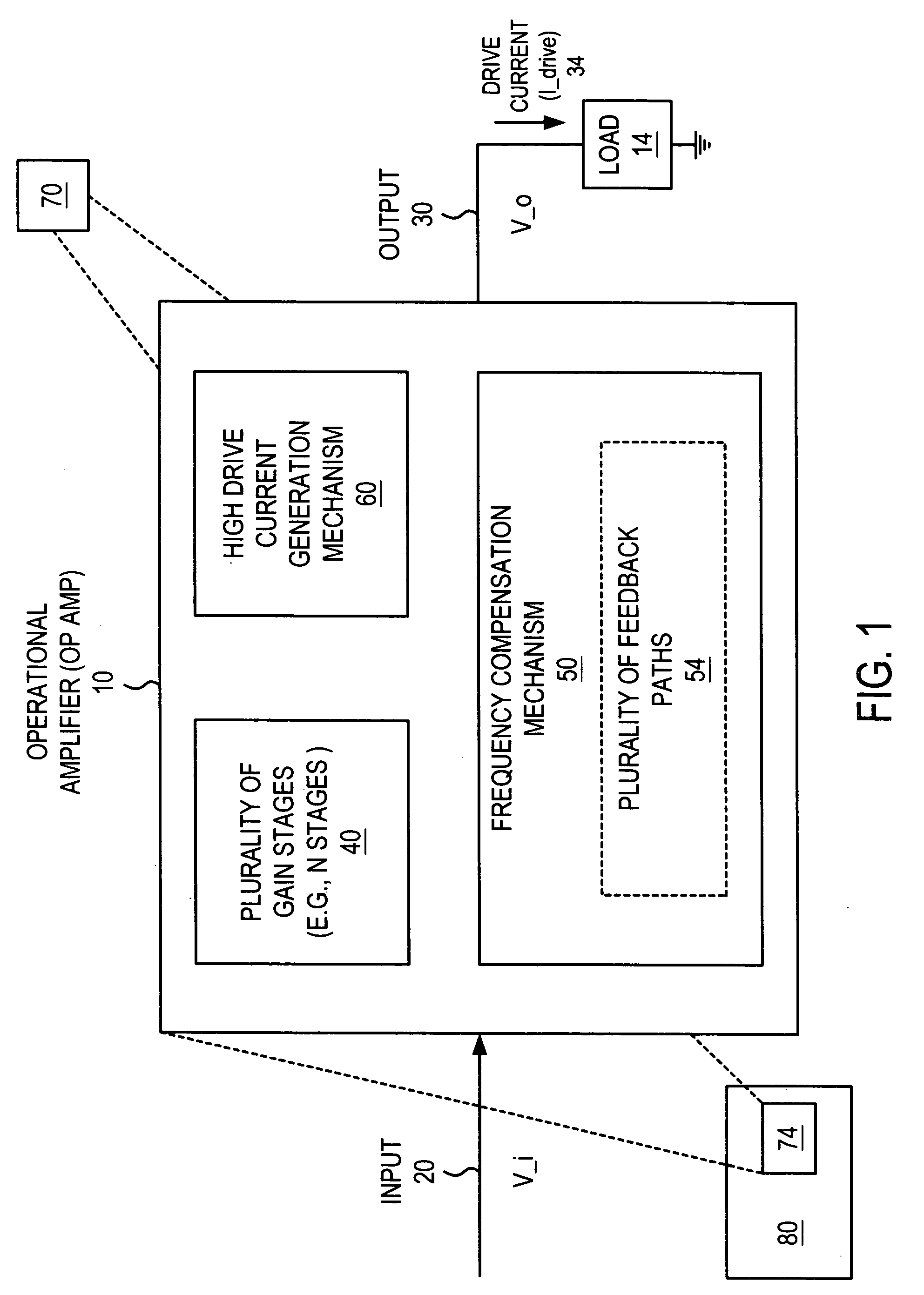
[0013] Operational Amplifier (Op Amp) 10

[0014]FIG. 1 illustrates an operational amplifier 10 according to one embodiment of the invention. The operational amplifier 10 (op amp) includes an input 20 that receives an input signal (e.g., an input voltage signal, V_i) and an output 30 that generates an output signal (e.g., an output voltage, V_o). The operational amplifier 10 also generates a drive current (I_drive) 34. The amplifier 10 can drive a ...


PUM


Abstract

An operational amplifier is described. The operational amplifier includes a first stage, a second stage, a third stage, and a fourth stage. The amplifier includes a nested transconductance-capacitance compensation configuration. The third stage includes class AB control mechanism. The fourth stage includes a class AB output stage.

Description

BACKGROUND OF THE INVENTION [0001] The operation amplifiers are useful in many different analog applications. For example, operational amplifiers are commonly found and utilized in communication systems. One application that requires operation amplifiers is a power line communications system. In such systems, the typical resistive loading is about a few ohms. [0002] In this environment, ordinary operational amplifiers are insufficient because prior art amplifiers do not provide sufficient drive current. Unfortunately, if a heavy resistive load is applied to this amplifier, the output stage current will be insufficient to drive the load unless the biasing current of the output stage is set at an unreasonable level. For example, prior art operational amplifiers that use a class A output is not suitable for driving the type of resistive load encountered in power line communication systems. [0003] Furthermore, in the design of multi-stage operational amplifiers instability and signal di...

Claims


Application Information

Patent Timeline
IPC IPC(8): H03F1/36
CPCH03F1/08H03F1/34H03F3/45183H03F3/45475H03F2200/153H03F2200/36H03F2203/45288H03F2203/45512H03F2203/45652
Inventor CHEN, LEILUM, RICHARD KOK KEONG
Owner AVAGO TECH INT SALES PTE LTD
Why Eureka
Eureka Blog
Learn More