Low noise high linearity downconverting mixer

Inactive Publication Date: 2007-03-15
ZHANG ZHAOFENG
View PDF8 Cites 0 Cited by
  • Summary
  • Abstract
  • Description
  • Claims
  • Application Information

AI Technical Summary

Benefits of technology

[0009] The purpose of the present invention is to introduce a low noise high linearity downconverting mixer circuit having a higher linearity, better system gain, and lower system noise.
[0010] The above purpose of present invention can be implemented as follows: A low noise high linearity downconverting mixer consists of a switch circuit, an intermediate frequency circuit, a RF amplifier circuit, and a bias current circuit. A DC current source is inserted in between the switch circuit and the intermediate frequency circuit to

Problems solved by technology

In the traditional Gilbert mixer, as shown in FIG. 1, when the input high RF signal is on the negative phase, since the reference current is zero, it

Method used


Image

  • Low noise high linearity downconverting mixer
  • Low noise high linearity downconverting mixer
  • Low noise high linearity downconverting mixer

Examples


Example

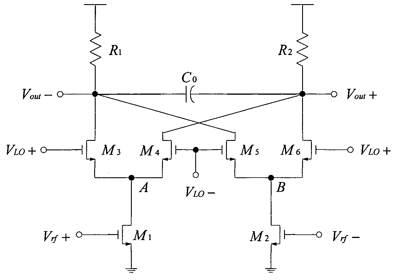
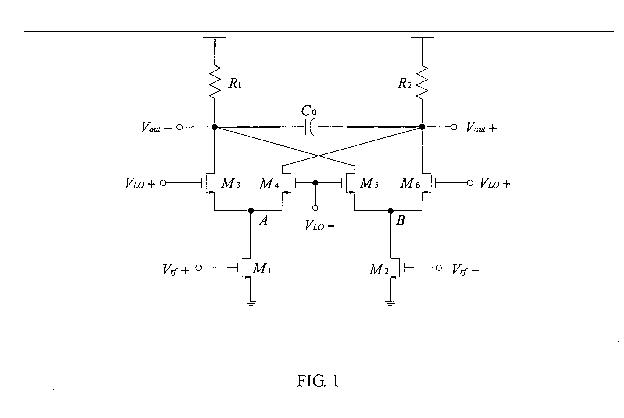
[0011] As shown in FIG. 1, the prior art Gilbert mixer circuit, having transistors M3, M4, M5 and M6 as switches, causes a very larger current through transistors. The circuit gain is limited as the loading resistance in this design cannot be high due to this very large current. Particularly when RF signals travel to transistors M1 and M2, M1 and M2 are possibly turned off when the input high RF signals are on the negative phase, causing distortion and directly affecting the quality of a mixer.

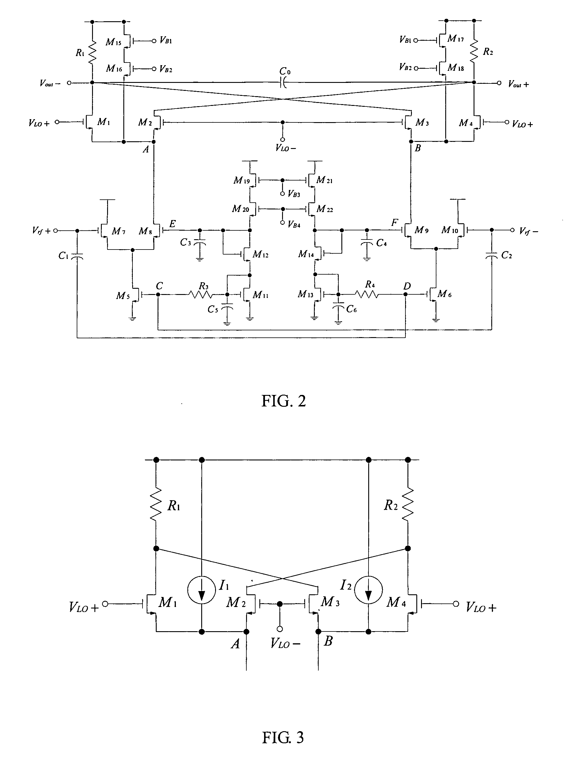
[0012]FIG. 2, FIG. 3, and FIG. 4 all show the low noise high linearity downconverting circuit in the present invention including the switch circuit, the intermediate frequency circuit, and the RF amplifier circuit. As shown in FIG. 2 and FIG. 3, the switch circuit and the intermediate frequency circuit are constructed by transistors M1, M2, M3, M4, DC current sources I1, I2, and resistance elements R1, R2. Such circuit connects to transistors M8 M9 at terminals A and B, while the followers M7...


PUM


Abstract

This invention presents a low noise high linearity downconverting mixer, comprising a switch circuit, an intermediate frequency IF circuit, a RF amplifier circuit, and a DC bias current circuit, whereas the present invention is used at RF front end in wireless communication devices.

Description

FIELD OF THE INVENTION [0001] The present invention relates to a low noise high linearity downconverting mixer, and more particularly to a mixer in the receiving device of a wireless radio frequency system. BACKGROUND OF THE INVENTION [0002] It is well known that mixer is one of the essential components among wireless RF system devices. Commonly mixer is used to convert a RF input signal into an intermediate frequency (IF) signal without signal distortion. It is so required a better system linearity, low noise and high amplified ratio. Linearity is an important specification to measure the quality of a mixer. In the traditional Gilbert mixer, as shown in FIG. 1, when the input high RF signal is on the negative phase, since the reference current is zero, it may turn MOS transistors M1 and M2 off, causing poor linearity. Also since the current via transistors are strong, loading resistance must not be high. It limits the system gain in a mixer, while having bad noise causing from tran...

Claims


Application Information

Patent Timeline
IPC IPC(8): H04B1/18
CPCH03D7/1441H03D2200/0084H03D7/1491H03D7/1458
Inventor ZHANG, ZHAOFENG
Owner ZHANG ZHAOFENG
Why Eureka
Try Eureka