Current detection method, current detection device, signal correction method for current detection device, and signal correction device for current detection device

Active Publication Date: 2017-10-26
HITACHI METALS LTD
View PDF3 Cites 0 Cited by
  • Summary
  • Abstract
  • Description
  • Claims
  • Application Information

AI Technical Summary

Benefits of technology

[0014]According to the invention, it is possible to make the relationship of output volta

Problems solved by technology

However, since the region with a linearly varying resistance is narrow, there

Method used


Image

  • Current detection method, current detection device, signal correction method for current detection device, and signal correction device for current detection device
  • Current detection method, current detection device, signal correction method for current detection device, and signal correction device for current detection device
  • Current detection method, current detection device, signal correction method for current detection device, and signal correction device for current detection device

Examples


Example

[0025]The first embodiment of the invention will be described below in reference to FIGS. 1A to 8.

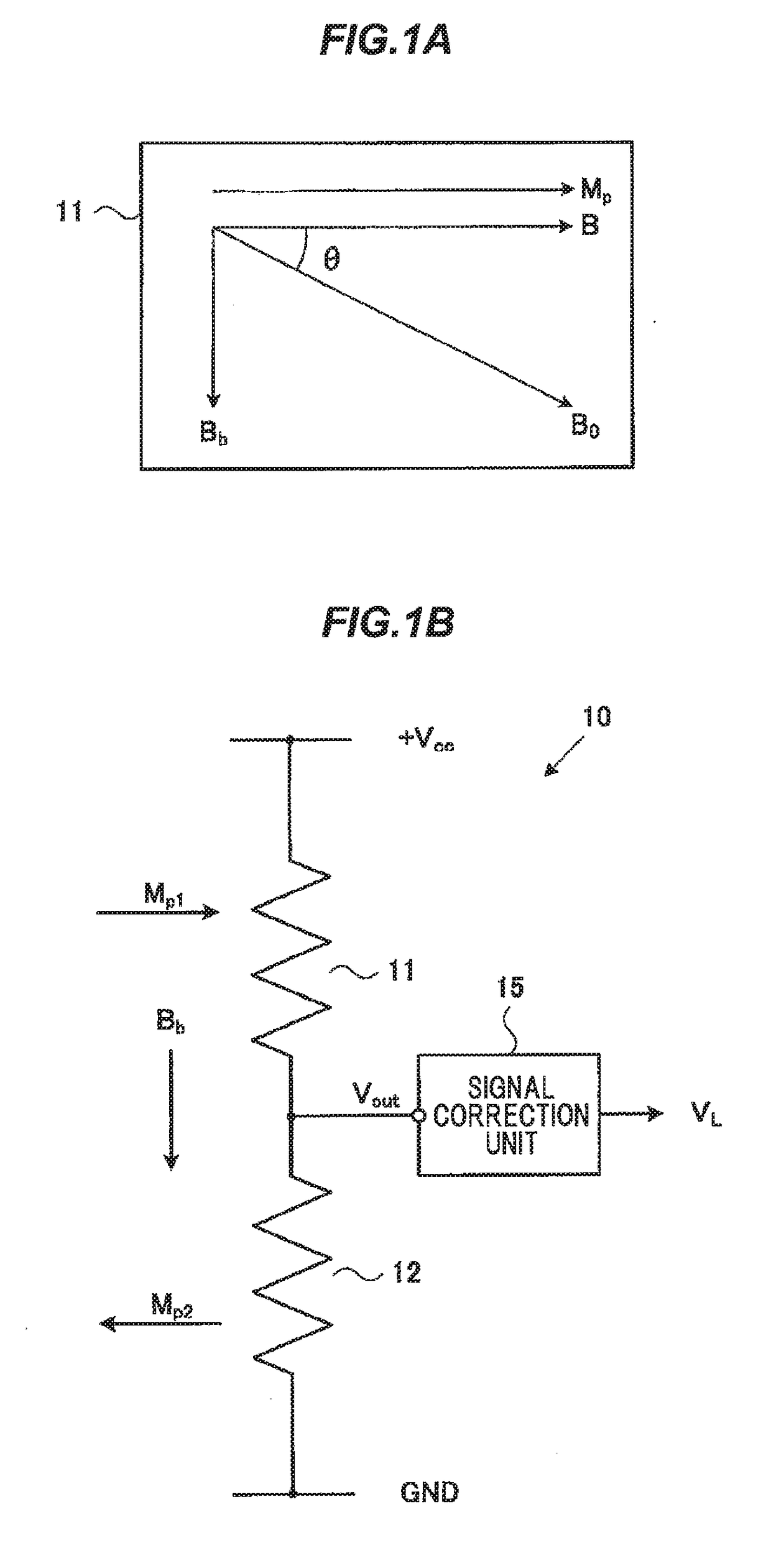
[0026]FIG. 1A is a diagram illustrating a magnetic detection principle of magnetism detection elements used in a current detection method, a current detection device and a signal correction method for the current detection device in the first embodiment of the invention. A magnetism detection element 11 is constructed from a GMR element. The magnetism detection element 11 is formed by laminating a magnetic pinned layer with a fixed magnetization direction Mp, a magnetic free layer with a magnetization direction θ varying depending on a bias magnetic field Bb applied in a direction substantially orthogonal to the magnetization direction Mp as well as depending on a measured electromagnetic field B, and a non-magnetic layer separating the magnetic pinned layer from the magnetic free layer. The measured electromagnetic field B is a magnetic field generated by an electric current to be meas...

Example

Second Embodiment

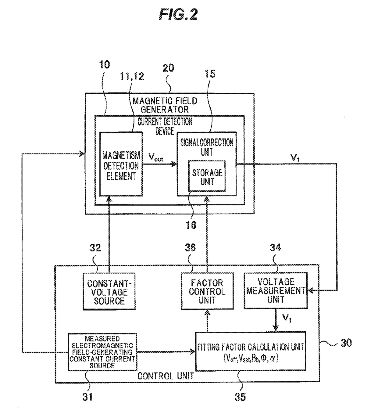
[0078]Next, the second embodiment of the invention will be described in reference to FIG. 9. FIG. 9 is a schematic diagram illustrating a configuration of the current detection method, the signal correction method for the current detection device and a signal correction device for the current detection device in the second embodiment of the invention, and corresponds to FIG. 2. A current detection device 10A and a control unit 30A in the second embodiment are configured differently from the current detection device 10 and the control unit 30 in the first embodiment, and the remaining configuration is the same. The configurations of the current detection device 10A and the control unit 30A which are the different features will be mainly described below. The same constituent elements as those of the first embodiment are denoted by the same reference numerals and the explanation thereof are omitted.

[0079]The current detection device 10A of FIG. 9 has the magnetism dete...


PUM


Abstract

A current detection method for a current detection device including magnetism detection elements that detect magnetic flux density and output a voltage signal corresponding to the magnetic flux density is provided. The method includes acquiring measured value data that is obtained as a result of providing magnetic flux density in a detectable range of the magnetism detection elements that indicates the relationship between the magnetic flux density and an output voltage signal from the current detection device. Next, computational processing is performed so as to fit the acquired measured value data to a formula that includes plural factors and indicates the output voltage of the magnetism detection elements, thereby calculating the plural factors, and correcting the output voltage signal from the magnetism detection elements in accordance with the calculated factors so as to be approximately linear with respect to the magnetic flux density. Finally, a corrected voltage signal obtained by the correction is outputted.

Description

CROSS-REFERENCE TO RELATED APPLICATIONS[0001]The present application is a U.S. National Phase of PCT / JP2014 / 077246 filed on Oct. 10, 2014. The disclosure of the PCT Application is hereby incorporated by reference into the present application.TECHNICAL FIELD[0002]The present invention relates to a current detection method and a current detection device for detecting a current value by measuring a magnetic field generated by an electric current flowing through a conductor, a signal correction method for the current detection device, and a signal correction device for the current detection device.BACKGROUND ART[0003]Conventional current detection devices are known, in which a magnetoresistance effect element(s) such as AMR element using the anisotropic magnetoresistive (AMR) effect or GMR element using the giant magnetoresistive (GMR) effect is / are used (see, e.g., PTL 1).[0004]The current detection device described in PTL 1 uses a method in which a magnetic field in a region with a re...

Claims


Application Information

Patent Timeline
IPC IPC(8): G01R15/20G01R33/09
CPCG01R33/09G01R15/20G01R33/093
Inventor FUTAKUCHI, NAOKICHIWATA, NAOFUMIAKIMOTO, KATSUYA
Owner HITACHI METALS LTD
Why Eureka
Try Eureka