

Image forming apparatus
a technology of forming apparatus and forming tube, which is applied in the direction of electrographic process, instruments, transportation and packaging, etc., can solve the problems of increasing cost and power consumption, complex apparatus,
- Summary
- Abstract
- Description
- Claims
- Application Information
AI Technical Summary
Benefits of technology
Problems solved by technology
Method used
Image

Examples
first embodiment
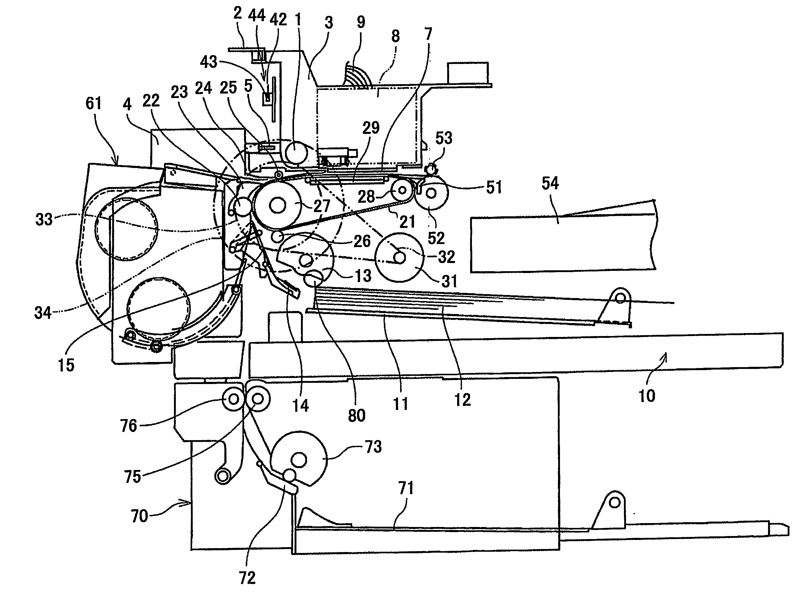
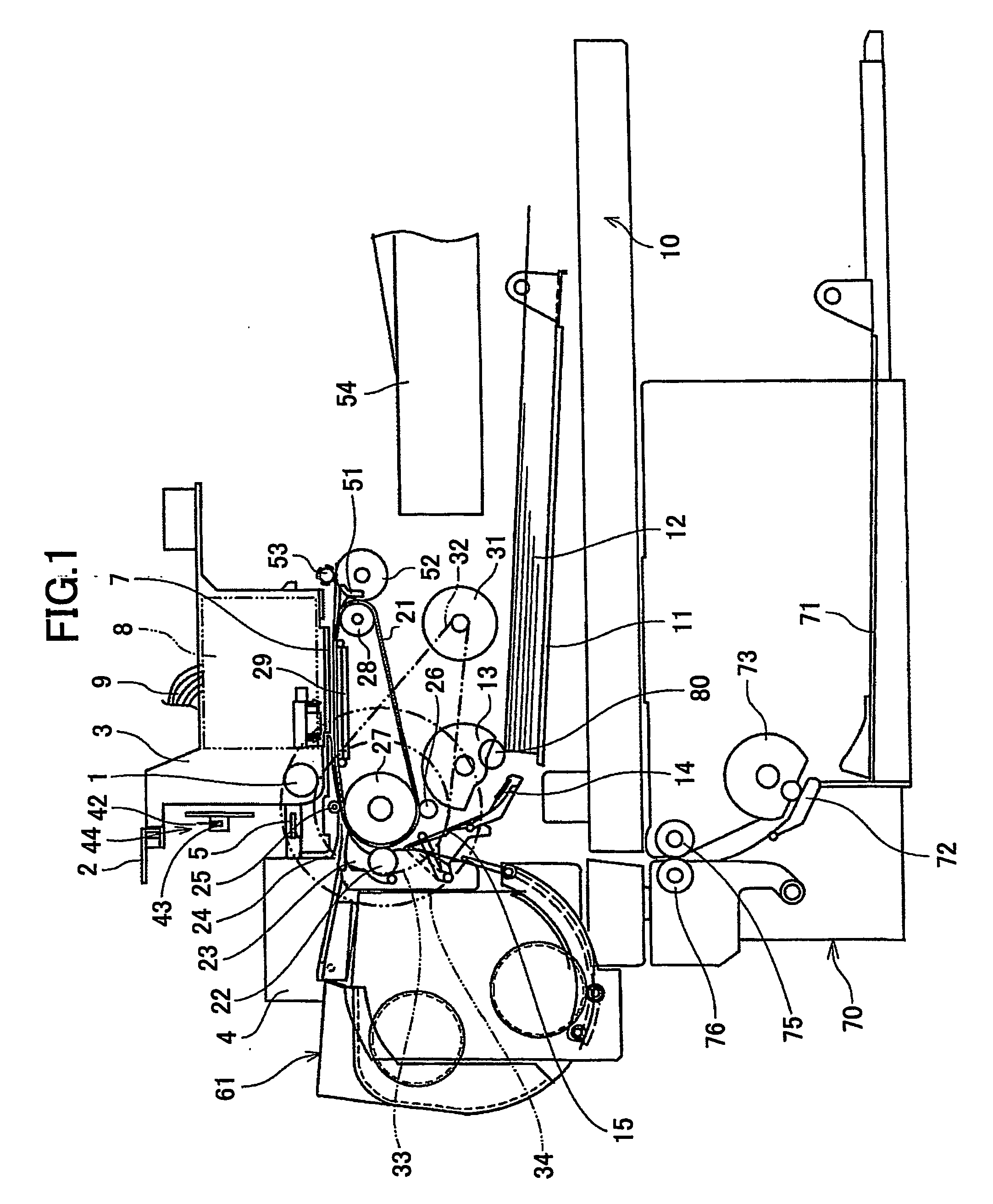
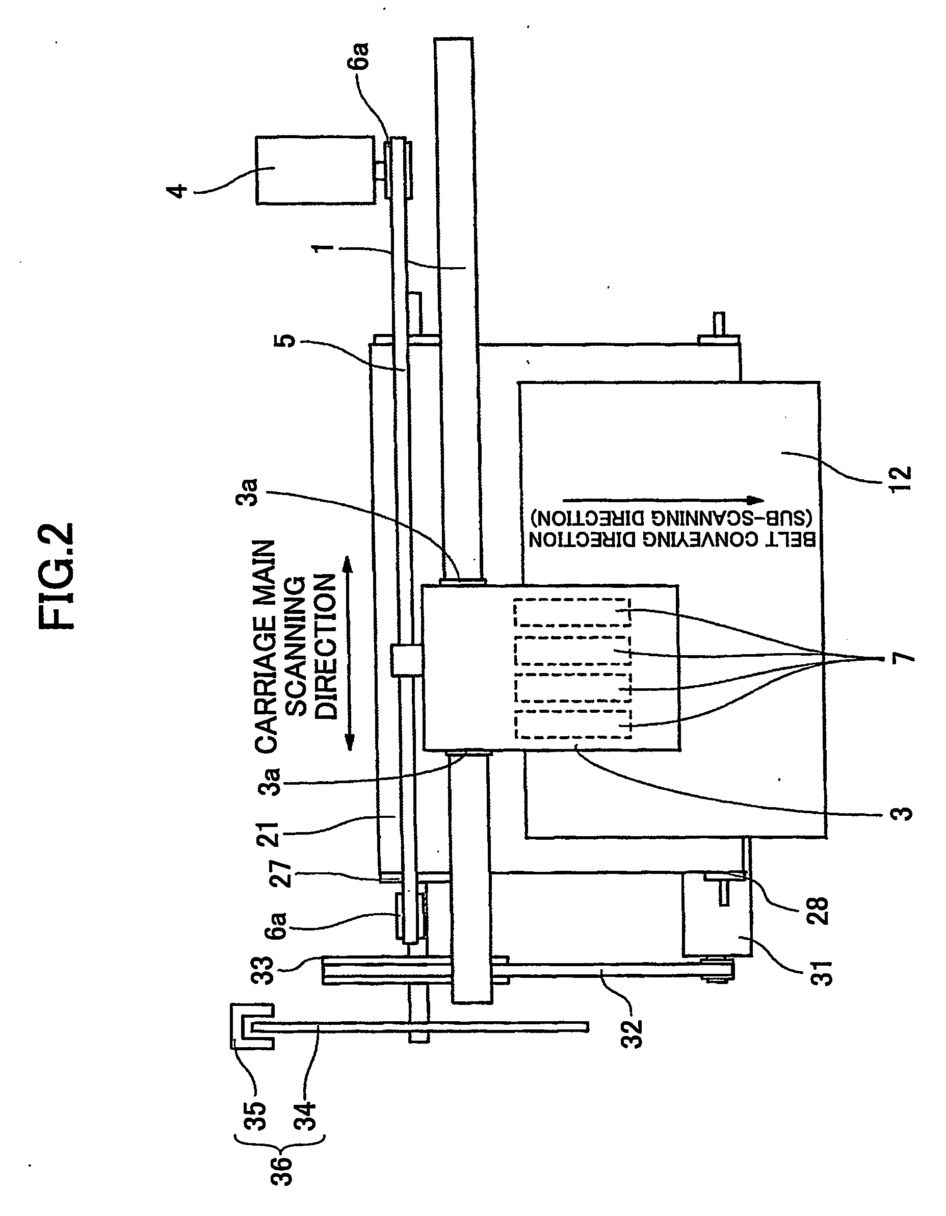
[0074] A description will now be given, with reference to the accompanying drawings, of embodiments according to the present invention. First, a description will be given, with reference to FIGS. 1 and 2, of an image forming apparatus according to the present invention. FIG. 1 is an illustrative side view of the image forming apparatus. FIG. 2 is a plan view of a part of the image forming apparatus shown in FIG. 1.
[0075] In the image forming apparatus shown in FIG. 1, a carriage 3 is slidably supported by a guide rod 1 and a guide rail 2 that bridge between left and right side plates (not shown in the figure) in a main scanning direction so that the carriage 3 is moved to scan in directions of arrows (the main scanning direction) in FIG. 2 by a main scanning motor via a timing belt being engaged with a drive pulley 6a and an idle pulley 6b. It should be noted that guide bushings (bearings) 3a are interposed between the carriage 3 and the guide rod 1, respectively.
[0076] Four record...
fifth embodiment
[0174] Therefore, the surface potential on the recording paper under the recording head 7 can be reduced by reducing the applied voltage. Since the applied voltage and the attraction force are related so that the attraction force is reduced if the applied voltage is reduced as shown in FIG. 32, it is difficult to reduce the applied voltage to an extremely small value. However, if a relationship between the resistance of a recording paper and the applied voltage, which gives an optimum value of the surface potential of the recording paper 12 is represented by table information and the applied voltage is changed in accordance with a portion of the recording paper 12 and a portion of the conveyance belt 21 (relative positional relationship) as in the above-mentioned fifth embodiment, a sufficient effect can be obtained.
[0175] A description will be given, with reference to FIG. 33, of a charge control process for the conveyance belt in the image forming apparatus according to the presen...
sixth embodiment
[0188] According to the above-mentioned process, the recording paper 12 is conveyed to the position under the recording head 7 with the conveyance time period (for example, 1.6 sec) exceeding the predetermined time period (for example, 0.4 sec) when the surface of the recording paper to be brought into the conveyance belt 21 is an image forming area (blank middle portion), and, thus, both the improvement of conveyance and the improvement of image quality can be simultaneously achieved at a higher level and the same effects as the above-mentioned fifth and sixth embodiment can be obtained. It should be noted that if both instructions are mixed, the instruction regarding the image forming area (blank middle portion) is given a priority so as to reduce the surface potential under the recording head 7 can be decreased to a value smaller than a predetermined surface potential, which enables improvement in both the conveyance and the image quality.
PUM
| Property | Measurement | Unit |
|---|---|---|
| Temperature | aaaaa | aaaaa |
| Length | aaaaa | aaaaa |
| Viscosity | aaaaa | aaaaa |
Abstract
Description
Claims
Application Information