
Wide dynamic range image sensor

a dynamic range, image sensor technology, applied in the direction of color television details, television system details, television systems, etc., can solve the problems of small displacement of the timing of the accumulation start point of signal charge in comparison with that of a comparable conventional method and increase in power consumption

Inactive Publication Date: 2007-05-10
NAT UNIV CORP SHIZUOKA UNIV
View PDF9 Cites 42 Cited by
  • Summary
  • Abstract
  • Description
  • Claims
  • Application Information

AI Technical Summary

Benefits of technology

[0006] On the other hand, in the burst reading, the reading time of signals of one horizontal line is reduced and the signal reading from all the pixels is performed in concentrated fashion in a short time. Supposing such a reading method, the signals must be read at high speed and, therefore, there is the problem that the power consumption increases and so forth. However, the displacement of the timing of the accumulation start point of signal charge is small in comparison with that of a comparable conventional method. Hence, there is the advantage that the distortion when an object that undergoes large movements is imaged is relatively small.
[0011] In addition, the present invention is an adaptive dynamic range image sensor that is capable of utilizing the fact that image information of long time accumulation and short time accumulation is obtained in frame units by means of the burst reading, of making settings while judging in real time the maximum value of a signal, whether the signal is saturated and, based on information of a histogram, the gain of the reading circuit, whether to perform burst reading with short time accumulation and very short time accumulation, and the corresponding accumulation times, and of performing imaging while settings are made in the optimum dynamic range.

Problems solved by technology

Supposing such a reading method, the signals must be read at high speed and, therefore, there is the problem that the power consumption increases and so forth.
However, the displacement of the timing of the accumulation start point of signal charge is small in comparison with that of a comparable conventional method.

Method used


Image

  • Wide dynamic range image sensor
  • Wide dynamic range image sensor
  • Wide dynamic range image sensor

Examples


Embodiment Construction

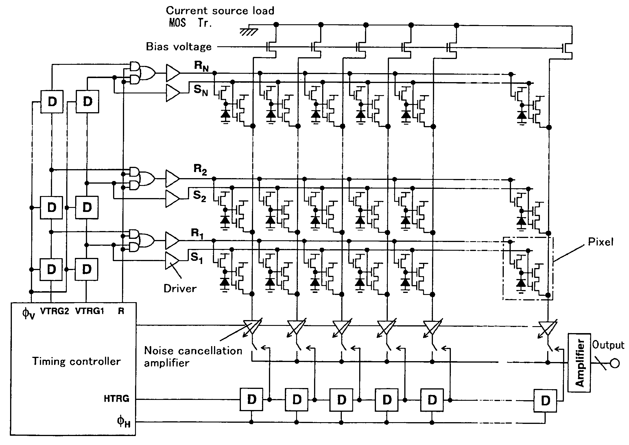
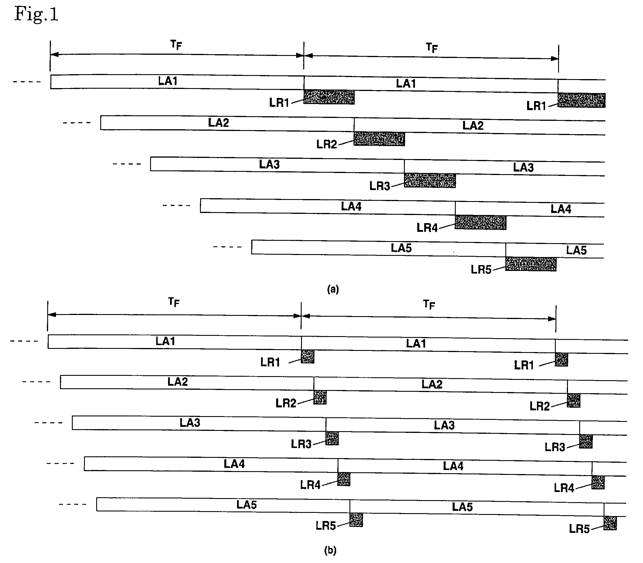
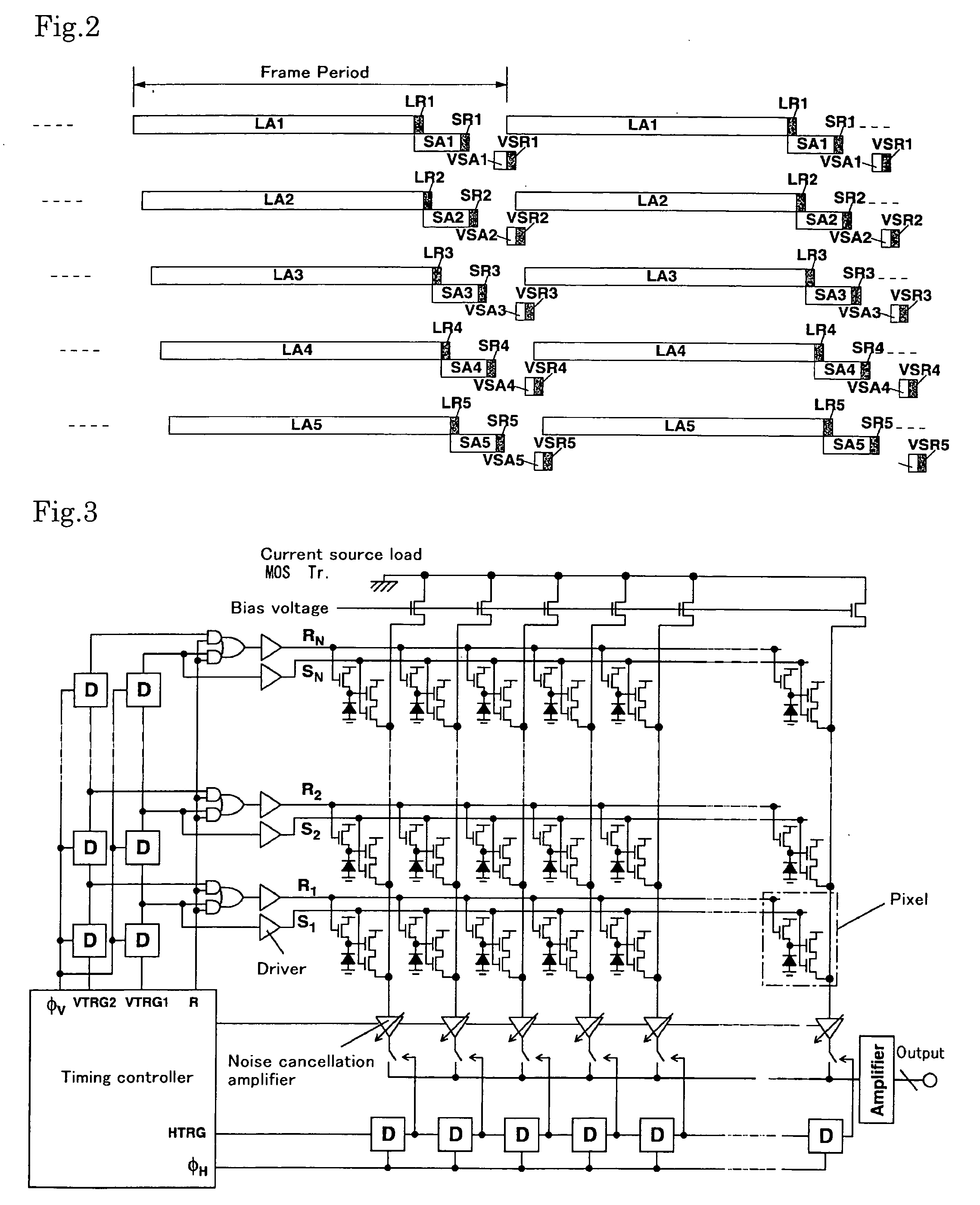
[0027] The present invention provides a wide dynamic range image sensor that has characteristics that solve the problems of the conventional technology. First, the present invention is based on the burst reading shown in FIG. 1B. On that basis, a wide dynamic range image sensor is implemented by reading and mixing signals of a plurality of accumulation times such as long time accumulation, short time accumulation, and accumulation of a shorter time. A timing chart for the accumulation and reading of signals of the wide dynamic range image sensor of the present invention is shown in FIG. 2. This example illustrates a case where the number of pixels in the vertical direction is five pixels. Suppose that the total time for reading signals rendered by means of long time accumulation is TR. A signal rendered by means of signal accumulation for the whole of the time rendered by deducting the time, during which long time accumulation is performed, from the frame cycle relating to each pixe...


PUM


Abstract

The present invention relates to a CMOS image sensor having a wide dynamic range, which permits favorable imaging even in cases where a bright portion and a dark portion exist simultaneously. The dynamic range can be widened by preventing the saturation of optical charge at a high illuminance by removing low illuminance signals due to long-time accumulation, intermediate illuminance signals due to short-time accumulation, and high illuminance signals due to ultra-short time accumulation from pixel portions of the image sensor. Further, adaptive control of the dynamic range can also be performed by dynamically changing the wide dynamic range imaging conditions that comprise a combination of different accumulation times of each of a plurality of short time accumulation signals.

Description

TECHNICAL FIELD [0001] The present invention relates to the widening of the dynamic range of an image sensor. BACKGROUND ART [0002] There exist a great number of conventional technologies for image sensors that have a wide dynamic range that permits favorable imaging even in cases where a very bright portion and a dark portion exist simultaneously. A large number of systems exist as processes that widen the dynamic range toward high illuminance on a CMOS image sensor. [0003] Proposed systems include (1) a system that calculates the number of clocks until a photodiode reaches a threshold value that is set from the outside by disposing a comparator and a coefficient unit in a pixel circuit, as disclosed in Japanese Patent Application Laid Open No. H7-274072, (2) a system that calculates the number of times a photodiode reaches a threshold value that is set from the outside in one frame cycle by disposing a comparator and a coefficient unit in a pixel circuit, as disclosed in Japanese ...

Claims


Application Information

Patent Timeline
IPC IPC(8): H04N5/217H04N5/235H04N5/335H04N5/353H04N5/355H04N5/369H04N5/374
CPCH04N5/235H04N5/2355H04N5/35581H04N5/378H04N23/70H04N23/741H04N25/589H04N25/78H04N25/75
Inventor KAWAHITO, SHOJI
Owner NAT UNIV CORP SHIZUOKA UNIV
Learn More