
Modulating apparatus, mobile communication system, modulating method, and communication method

a technology of modulating apparatus and mobile communication system, applied in the field of modulating apparatus, mobile communication system, modulating method, communication method, can solve the problems of extremely low spectrum efficiency of land mobile radio system in the united states, inability to use nonlinear power amplifiers in the present lmr system, and inability to solve the problems described below

Active Publication Date: 2007-05-10
JVC KENWOOD CORP A CORP OF JAPAN
View PDF9 Cites 4 Cited by
  • Summary
  • Abstract
  • Description
  • Claims
  • Application Information

AI Technical Summary

Benefits of technology

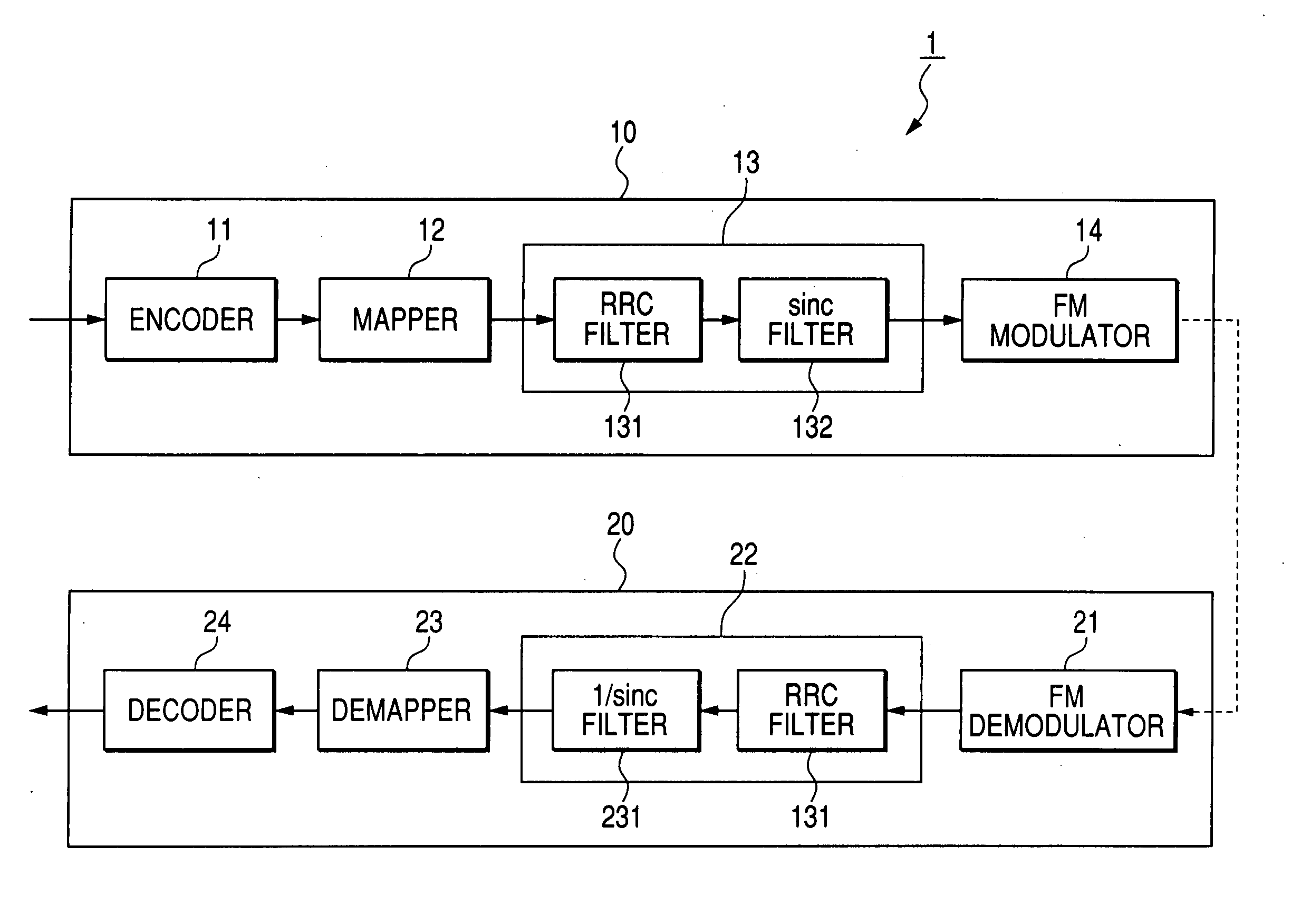
[0033] In order to attain the object, a communication method according to a fourth aspect of the invention is a communication method in a mobile communication system including: a transmitter that performs transmission of data at a transmission rate of 2400×(n+1) (n: natural number) [bps]; and a receiver that receives data transmitted from the transmitter. The communication method includes: an encoding step of encoding predetermined data to generate a binary signal; a symbol converting step of sequentially converting a binary signal generated by the encoding step into a 2(n+1)-ary symbol, which includes (2(n+1)+1−2k) (1≦k≦2(n+1)) values, (n+1) bits at a time and outputting the symbol; a step of blocking an unnecessary frequency component of a symbol inputted from the symbol converting step and outputting a waveform signal; a frequency shifting and modulating (FM) step of transmitting a signal, which is obtained by shifting to modulate a frequency according to a magnitude of an amplitude of the waveform signal inputted from the first base band filter, to the receiver; a demodulating step of demodulating the signal transmitted from the transmitter and received and outputting a 2(n+1)-ary signal; a step of blocking an unnecessary frequency component of the 2(n+1)-ary signal outputted from the demodulating step and outputting the 2(n+1)-ary signal; a binary signal converting step of sequentially converting a 2(n+1)-ary signal inputted into a binary signal of (n+1) bits and outputting the binary signal; and a decoding step of decoding a binary signal inputted from the binary signal generating step and outputting the predetermined data. When a symbol of ±(2(n+1)−1) is outputted from the symbol converting step, a frequency shift of a signal outputted from the frequency shifting and modulating step is set to take a value in a range of ±0.822[kHz] to ±0.952[kHz].

Problems solved by technology

Conventionally, the Land Mobile Radio (LMR) system in the United States has extremely low spectrum efficiency because frequencies are allocated to respective channels at extremely wide channel spacing such as 25 kHz or 30 kHz.
However, since the π / 4QPSK modulation system is a linear modulation system, problems described below occur.
It is impossible to use a nonlinear power amplifier used in the present LMR system.
In order to use a linear power amplifier in the LMR system, since an additional circuit such as a linearizer is required, a space and cost for the LMR system increase.
Since the linear power amplifier has lower efficiency and a larger consumed current compared with the nonlinear power amplifier, heat generation in a radio apparatus constituting the LMR system causes a problem.
Moreover, in a portable LMR system, since the portable LMR system is driven by a battery, an operation time decreases.
In addition, it is extremely difficult to make a mounting space and cost of a nonlinear power amplifier equivalent to those of the non-linear power amplifier.
Therefore, it is not realistic to apply the linear modulation system represented by the P25-P2 modulation system to the LMR system applicable to the channel spacing of 6.25 kHz.

Method used


Image

  • Modulating apparatus, mobile communication system, modulating method, and communication method
  • Modulating apparatus, mobile communication system, modulating method, and communication method
  • Modulating apparatus, mobile communication system, modulating method, and communication method

Examples


first embodiment

[0087] First, a transmission rate, a symbol rate, a base band filter, a modulation system, and a nominal frequency shift in the first embodiment are shown in Table 9 below.

TABLE 9Transmission Rate4800 bpsSymbol Rate2400 symbol / sBase Band FilterTransmission: A filter obtained bycombining a filter having a RootRaised Cosine characteristic withan arbitrary α and a filter havinga sinc function characteristicReception: A filter obtained bycombining a filter having a RootRaised Cosine characteristic withan arbitrary α and a filter havinga 1 / sinc function characteristicModulation SystemQuaternary FSK Modulation SystemNominal FrequencyArbitrary in ranges +3 = +913 Hz toShift+1057 Hz and −3 = −913 Hz to −1057 Hzwith respect to respective foursymbol levels (±3, ±1)+1 and −1 are shifts ⅓ of +3 and−3, respectively

[0088]FIG. 12 is a block diagram showing a constitution of a ground mobile communication system 1 according the first embodiment of the invention. The ground mobile communication sys...

second embodiment

[0116] A second embodiment will be explained. A transmission speed, a symbol rate, a base band filter, a modulation system, and a nominal frequency shift in the second embodiment are shown in Table 10 below.

TABLE 10Transmission Rate4800 bpsSymbol Rate2400 symbol / sBase Band FilterTransmission: A filter having aRoot Raised Cosine characteristicwith an arbitrary αReception: A filter having a RootRaised Cosine characteristic withan arbitrary αModulation SystemQuaternary FSK Modulation SystemNominal FrequencyArbitrary in ranges +3 = +581 Hz toShift+673 Hz and −3 = −581 Hz to −673 Hzwith respect to respective foursymbol levels (±3, ±1)+1 and −1 are shifts ⅓ of +3 and−3, respectively

[0117]FIG. 16 is a block diagram showing a constitution of a ground mobile communication system 2 according to the second embodiment of the invention. The ground mobile communication system 2 schematically includes a transmitting unit 30 and a receiving unit 40. Components identical with those in the first em...


PUM


Abstract

An encoder encodes sound data and the like to generate a binary signal. A mapper converts the binary signal into a quaternary symbol and outputs the quaternary symbol. A base band filter includes a root raised cosine filter and a sinc filter. The base band filter blocks a predetermined frequency component of a symbol to shape the symbol into a waveform signal and outputs the waveform signal shaped. An FM modulator transmits a signal subjected to FM modulation according to a magnitude of an amplitude of a waveform signal to a receiving unit. When a symbol of ±3 is outputted from the mapper, a frequency shift of a signal transmitted from the FM modulator has a predetermined value in a range of ±0.822[kHz] to ±0.952[kHz]. This makes it possible to provide a modulating apparatus, a mobile communication system, a modulating method, and a communication method that use a modulating method that can conform to the FCC rule to be enforced in 2005 without using a linear power amplifier.

Description

TECHNICAL FIELD [0001] The present invention relates to a modulating apparatus, a mobile communication system, a modulating method, and a communication method, and more particularly, to a modulating apparatus, a mobile communication system, a modulating method, and a communication method that can conform to the FCC rule to be enforced in 2005 without using a linear power amplifier. BACKGROUND ART [0002] Conventionally, the Land Mobile Radio (LMR) system in the United States has extremely low spectrum efficiency because frequencies are allocated to respective channels at extremely wide channel spacing such as 25 kHz or 30 kHz. To improve this spectrum efficiency, the Federal Communications Commission (FCC) of the United States provided in the FCC rule that, from 1997, the channel spacing be changed to 12.5 kHz that was half the conventional spectrum efficiency. Consequently, the LMR system was operated at the channel spacing of 25 kHz or 12.5 kHz. This change of the channel spacing i...

Claims


Application Information

Patent Timeline
IPC IPC(8): H04L27/00H04L25/03H04L27/12
CPCH04L25/03834H04L27/12
Inventor TANIGUCHI, MASARU
Owner JVC KENWOOD CORP A CORP OF JAPAN
Learn More