Eureka AIR delivers breakthrough ideas for toughest innovation challenges, trusted by R&D personnel around the world.

Electrical connector with a bifurcated contact

Active Publication Date: 2007-05-10
APTIV TECH LTD
View PDF6 Cites 5 Cited by
  • Summary
  • Abstract
  • Description
  • Claims
  • Application Information

AI Technical Summary

Benefits of technology

[0005] The possibility now exists due to this design of providing the bifurcated contact with an electrically conductive jacket which provides an additional current path without enlarging the constructional height and thus reduces the generation of heat. This electrically conductive jacket can also comprise two limb-like sections, for example, just like the bifurcated contact. A further current path can therefore be provided, for example, with the electrically conductive jacket between a relay contact and a central electrical interface, for example, which was not possible with the previously usual additional sleeve of stainless steel to increase the normal contact force. The circumstance can thus therefore in particular also be taken into account that different load currents can occur in the central electrical system. Since the constructional height is not enlarged by the electrically conductive jacket, additional costs are saved. Advantages also result with respect to the respective installation situation with the small constructional height.
[0006] Additional contact points to the mating plug of, for example, a relay or a fuse are therefore produced with the electrically conductive jacket without enlarging the constructional height, and indeed with the positive effect of a reduction of the heat development in the central electrical system and of improved current carrying capacity. The electrically conductive jacket forms an additional bridge between the mating piece such as a relay or a fuse and, for example, a conductor rail to which the bifurcated contact can be connected.
[0016] In a preferred practical embodiment, the jacket consists of a copper plastic alloy. The jacket should preferably have good electrical conductivity and good thermal relaxation stability.

Problems solved by technology

Since the constructional height is not enlarged by the electrically conductive jacket, additional costs are saved.
Advantages also result with respect to the respective installation situation with the small constructional height.

Method used


Image

  • Electrical connector with a bifurcated contact
  • Electrical connector with a bifurcated contact
  • Electrical connector with a bifurcated contact

Examples


Embodiment Construction

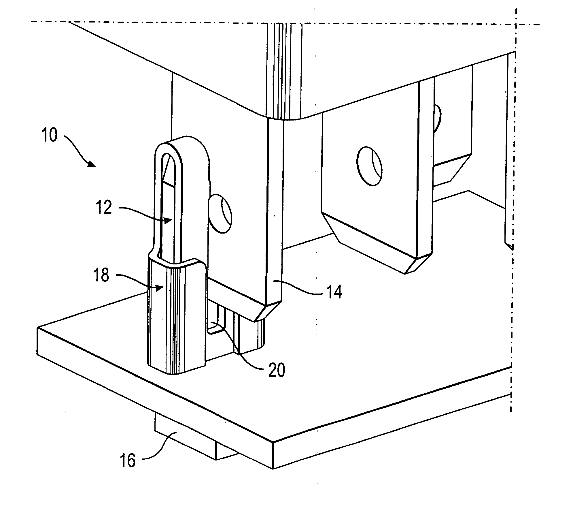
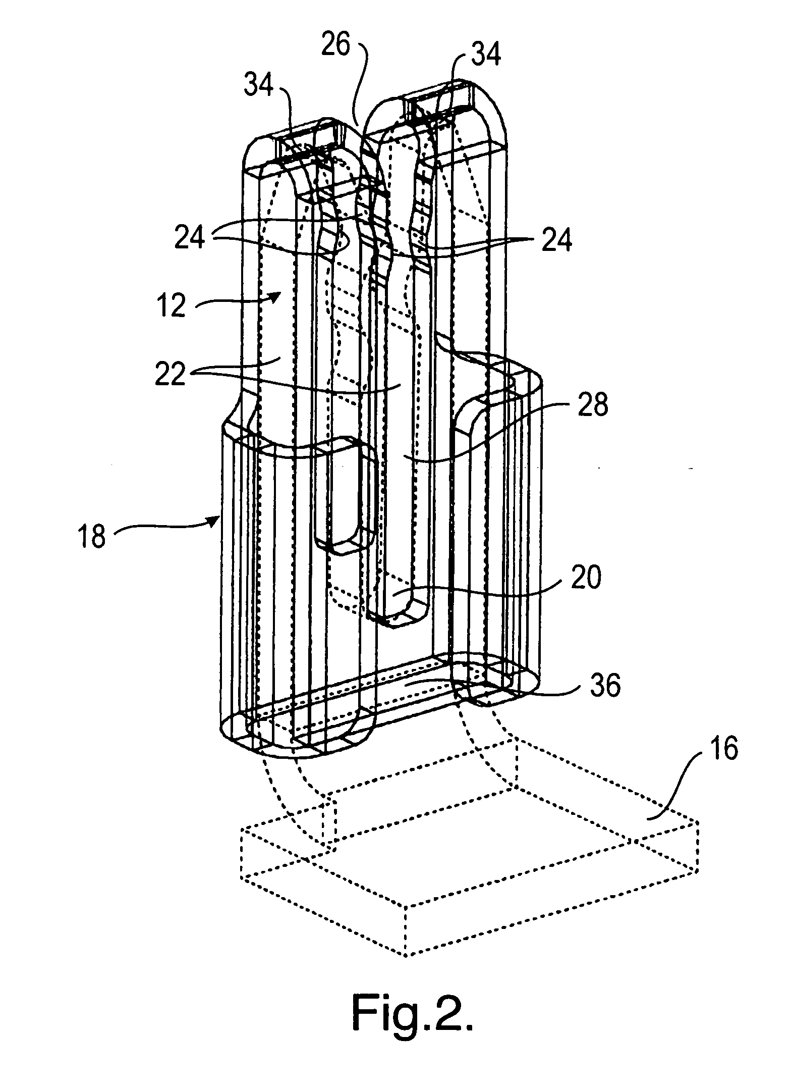
[0027]FIG. 1 shows in a schematic perspective representation an electrical connection device 10 comprising a bifurcated contact 12 to establish an electrical connection with a mating contact 14.

[0028] The cable contact 12 can be connected to a current conductor 16. The mating contact 14, for example of tongue form in the present case, can be associated, for example, with a relay, a fuse or the like.

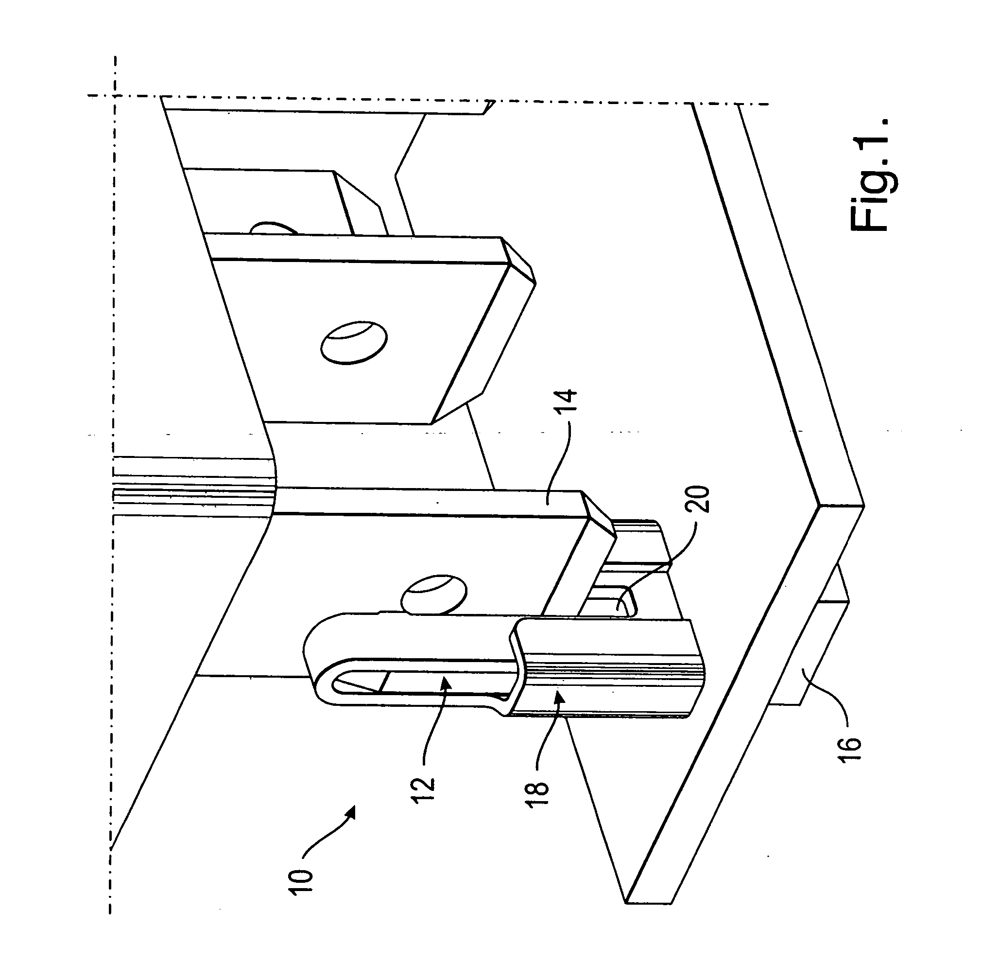
[0029] The bifurcated contact 12 is provided with an electrically conductive jacket 18. This jacket 18 can in particular be in contact with the web region 20 of the bifurcated contact 12 (cf. e.g. the contact regions 38 in FIG. 3), on the one hand, whereas, in the regions in which it surrounds the two limbs 22 (cf. in particular FIG. 2) of the bifurcated contact 12, it has contact positions with the mating contact 14, on the other hand, which are formed in the present case by shoulders 24 (cf. in particular FIG. 2 again).

[0030] In FIG. 2, the bifurcated contact 12 recognizable in FIG. ...


PUM


Abstract

An electrical connection device comprises a bifurcated contact to establish an electrical connection with a mating contact, the bifurcated contact having at least two limbs, at least one web region between the limbs, and an electrically conductive jacket that is in contact with said web region. The bifurcated contact includes a region wherein the jacket at least partially surrounds the two limbs, which provide a plurality of contact positions within the jacket.

Description

TECHNICAL FIELD [0001] The invention relates to an electrical connection device comprising a bifurcated contact for the establishing of an electrical connection with a mating contact. BACKGROUND OF THE INVENTION [0002] Bifurcated contacts, that is contacts with two contact limbs or contact sections which can be arranged, for example, in an upright or horizontal manner, frequently serve for the establishing of an electrical connection and a mechanical connection with a tongue-like mating contact. In this arrangement, this mating contact can, for example, be associated with a relay, a fuse and / or the like. The limited current carrying capacity due to the increased heat development in the bifurcated contact is disadvantageous with such a connection. Conventional solutions which make up for this disadvantage result in a larger construction height. SUMMARY OF THE INVENTION [0003] It is the underlying object of the invention to provide an improved electrical connection device of the initi...

Claims


Application Information

Patent Timeline
IPC IPC(8): H01R29/00
CPCH01R13/115H01R2201/26H01R13/112
Inventor CVASA, EDUARD
Owner APTIV TECH LTD
Why Eureka
Eureka Blog
Learn More