Board standoff device for electrical connector assembly

a technology for electrical connectors and standoff devices, which is applied in the direction of coupling device connections, coupling parts engagement/disengagement, electrical apparatus, etc., can solve the problems of increasing manufacturing costs, inability to adapt, and inconvenience for the manufacturer of products, so as to facilitate heat removal during operation and save space

Inactive Publication Date: 2007-05-10
ADVANCED CONNECTEK INC
View PDF26 Cites 20 Cited by
  • Summary
  • Abstract
  • Description
  • Claims
  • Application Information

AI Technical Summary

Benefits of technology

[0006] It is therefore one object of the present invention to provide a board standoff device for electric

Problems solved by technology

In short, it is not adaptable.
Thus, a manufacturer of the product may be bothered by the problem of stor

Method used


Image

  • Board standoff device for electrical connector assembly
  • Board standoff device for electrical connector assembly
  • Board standoff device for electrical connector assembly

Examples


Embodiment Construction

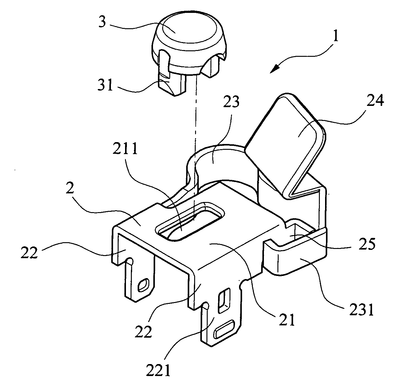
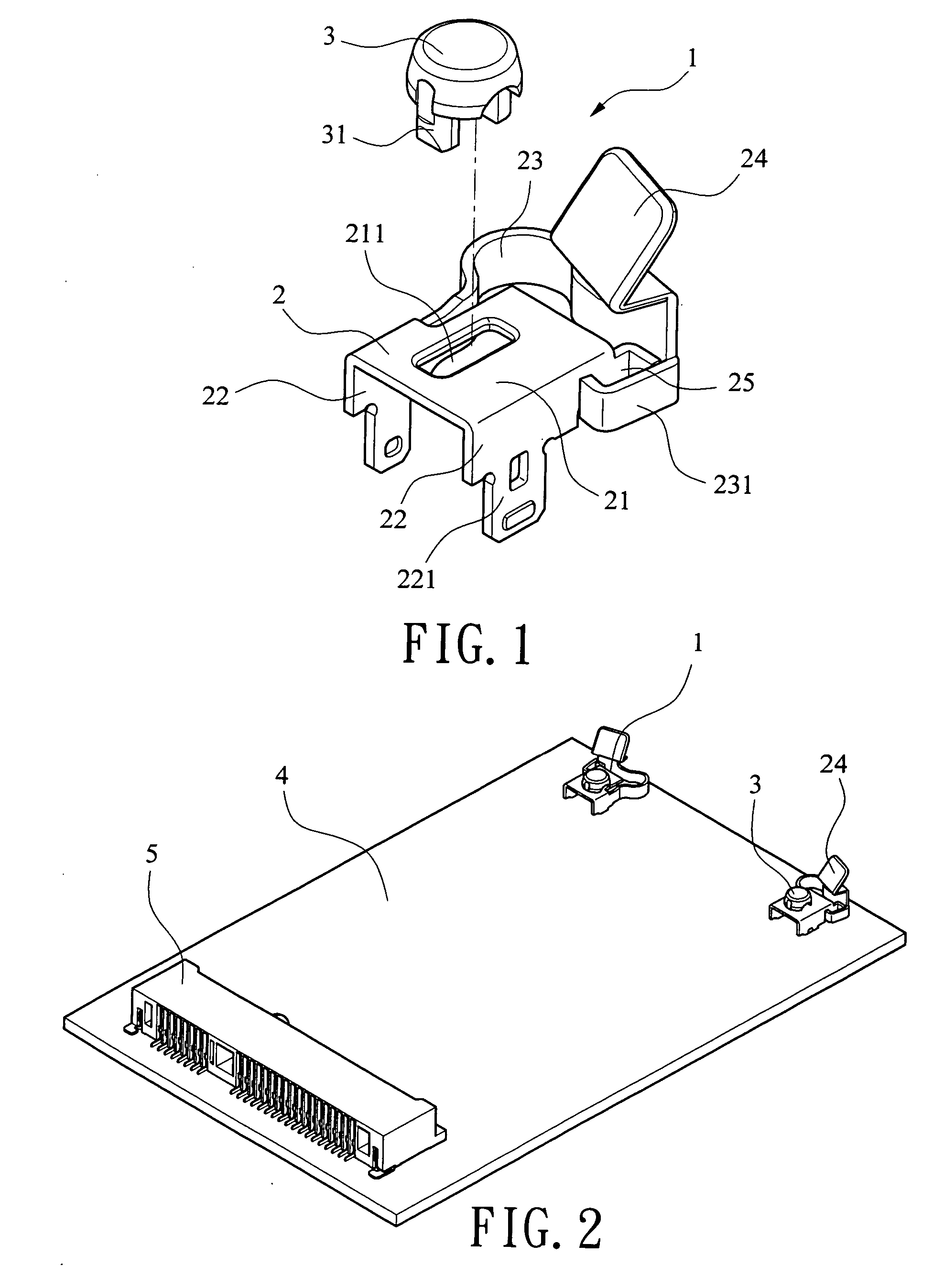
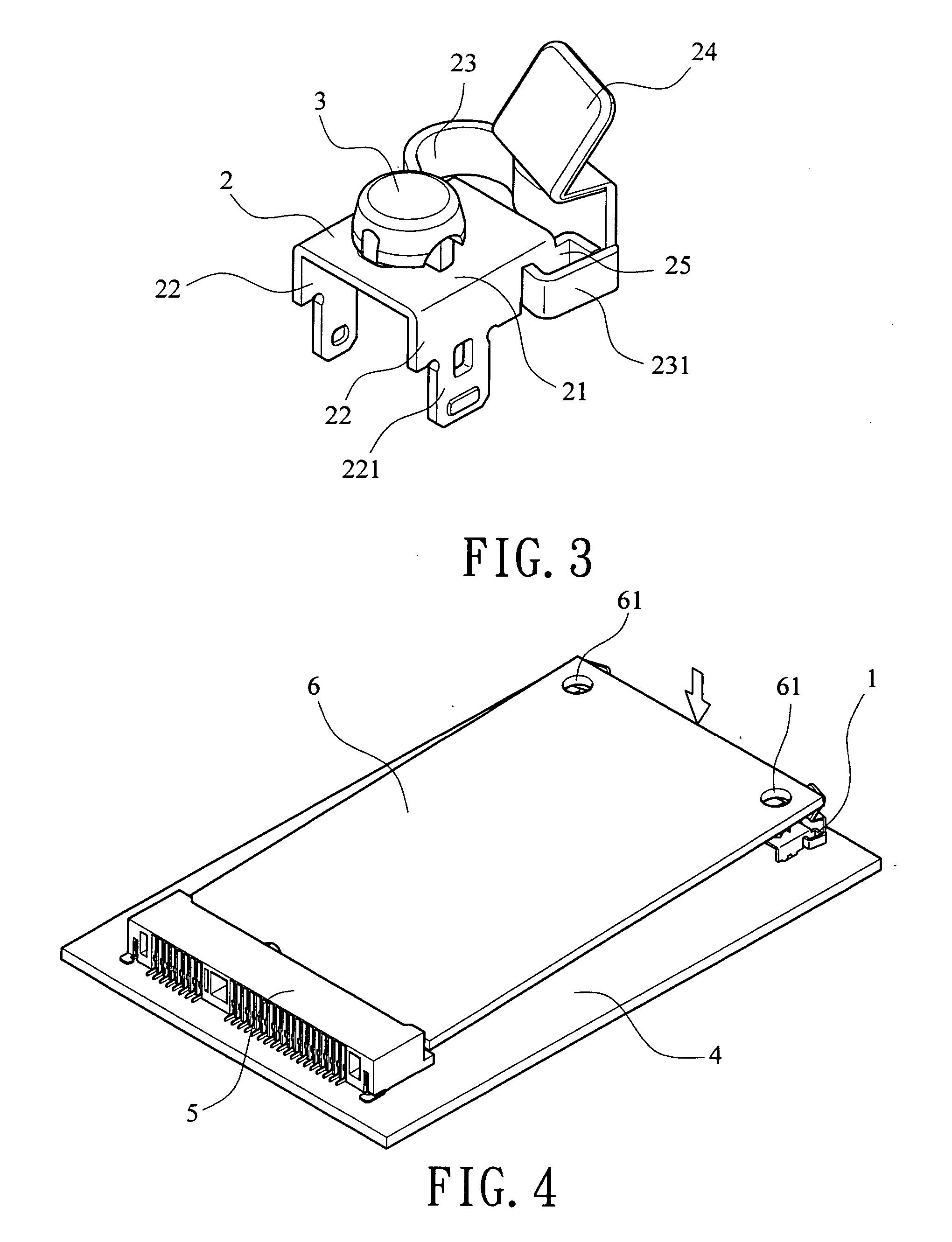
[0021] Referring to FIGS. 1 to 4, an electrical connector assembly having two board standoff members 1 each constructed in accordance with a first preferred embodiment of the invention is shown. The board standoff member 1 comprises a body 2 of inverted U-section and a detachable locating member 3. Each component is discussed in detailed below.

[0022] The body 2 comprises a top surface 21 having a substantially rectangular opening 211, two legs 22 formed by two opposite vertical portions of the body 2, each leg 22 having a lead-in portion 221 extended downward, a flexible arc-shaped member 23 extended rearward from a joining portion of one leg 22 and the top surface 21, the arc-shaped member 23 having a resilient arm 231 having its end disposed in close proximity to the other leg 22, an inclined latch 24 extended upward from an intermediate portion of the arc-shaped member 23, and a bent tab 25 extended laterally to be in close proximity to the arm 231.

[0023] The button-like locati...


PUM


Abstract

A board standoff device for mounting a first circuit board (e.g., daughter card) on a second circuit board (e.g., mother board) of an electrical connector assembly is disclosed. The first circuit board has a front end pivotably secured to a card edge connector mounted on a top surface of the second circuit board adjacent a front end thereof. The board standoff device is located around a rear end of the electrical connector assembly and includes at least one unit. Each unit includes a body fastened on the second circuit board, the body including an upward inclined latch, and a locating member detachably secured onto the body. A rear end of the first circuit board is fastened between and by the locating member and the latch of each unit. The invention can save space, facilitate heat removal during operation, and is highly adaptable and durable.

Description

BACKGROUND OF THE INVENTION [0001] 1. Field of Invention [0002] The present invention relates to electrical connector assemblies, and more particularly to a board standoff member for detachably supporting one circuit board on the other circuit board of an electrical connector assembly. [0003] 2. Description of Related Art [0004] Card edge connectors, for example, such as PCI (Peripheral Component Interface) and PCI Express connectors, are widely employed to connect a daughter card to a mother board. For example, U.S. Patent Application Publication No. US 2005 / 0164540 A1 discloses an electrical connector assembly having board hold down. Each of the board hold downs is stamped and formed from a sheet of metal. The board hold down comprises an arc-shaped body, an upward locating portion having a conic lead-in securely inserted into an engaging hole of a daughter card, two legs securely inserted into retention holes of a mother board, an anti-overstress portion extended from one end of ...

Claims


Application Information

Patent Timeline
IPC IPC(8): H01R13/62
CPCH05K7/142H01R12/7005H01R12/721
Inventor WANG, MEI HUI
Owner ADVANCED CONNECTEK INC
Why Eureka
Try Eureka