Inspection system for a turbine blade region of a turbine engine

a technology of inspection system and turbine engine, which is applied in the direction of machines/engines, mechanical equipment, instruments, etc., can solve the problems that the inner housing and outer housing are often difficult to remove from the installed position, and achieve the effect of reducing the stress

Inactive Publication Date: 2007-05-17
SIEMENS ENERGY INC
View PDF15 Cites 40 Cited by
  • Summary
  • Abstract
  • Description
  • Claims
  • Application Information

AI Technical Summary

Benefits of technology

[0004] This invention relates to an inspection system formed from at least one viewing tube for viewing components of a turbine engine during operation of a turbine engine. For example, the viewing tube may extend between an outer turbine cylinder and a blade ring enabling a turbine blade assembly, and more particularly, a turbine blade, to be viewed. The viewing tube of the inspection system may be formed from at least one receiver coupled to a component of a turbine engine proximate to a turbine blade assembly and at least one support housing coupled to an outer surface of an outer turbine cylinder. In at least one embodiment, the component the receiver is coupled to is a blade ring. The inspection system may also include at least one generally elongated outer housing extending at least from the support housing coupled to an outer surface of an outer turbine cylinder through the at least one receiver coupled to a component of a turbine engine. The outer housing may be biased towards the at least one receiver to seal the outer housing to the receiver. The outer housing may be supported with a bearing, which may be a spherical hollow bearing, that is coupled to an outer surface of the outer housing and bears against an inner surface of the support housing enabling axial movement of the housing. The bearing may be seated in an indentation, which may be a semi-toroidal indentation, in the inner surface of the support housing. The bearing can form a ball and socket type connection enabling the viewing tube to move relative to the turbine engine components to which the viewing tube is attached, thereby reducing the stresses imparted by the turbine engine on the viewing tube during operation of the turbine engine.
[0005] The viewing tube may also include an inner housing positioned within the outer housing and biased toward the receiver. In at least one embodiment, the inner housing is generally cylindrical and positioned concentrically within the outer housing. The inner housing may contain a plurality of optical lenses. The optical lenses may be positioned at various locations depending on the application. The optical lenses may be infrared lenses or other appropriate lenses. In at least one embodiment, the optical lenses may be positioned within an optical lens housing positioned within the inner housing. The optical lens housing may facilitate easy removal, maintenance, and replacement of the lenses, if necessary. More specifically, the inner housing and outer housing are often difficult to remove from an installed position in a turbine engine after the turbine engine has been run as the housings often have tight tolerances and interference fits with adjacent components. However, the optical lens housing may be easily removed and thus, may enable the lenses to be easily maintained.
[0006] The inspection system may also include a substantially sealed end at the end of the viewing tube proximate to the receiver. The sealed end may include an aperture enabling components of a turbine engine to be viewed. In addition, the aperture provides a gas pathway between internal aspects of the viewing tube and outside of the viewing tube. The viewing tube may also have a pressure gradient relative to areas outside of the viewing tube such that a higher pressure exists within internal aspects of viewing tube than outside the viewing tube. During operation, gases, which may be cooling air, flow from within the viewing tube out of the aperture in the sealed end proximate the receiver. This gas flow substantially prevents contaminants from entering the viewing tube and harming the optical lenses container therein.
[0008] An advantage of the inspection system is that the bearing forming the ball and socket type connection between the outer housing and the support housing shields the outer housing and optical lenses contained therein from harmful stresses developed within a turbine engine during operation. The bearing enables the viewing tube to swivel around the pivot point at the bearing relative to the turbine engine.
[0009] Another advantage of this invention is the aperture in the sealed end proximate the receiver enables gases at a higher pressure contained within the outer housing to bleed out of the inspection system and thereby prevent contamination of the optical lenses contained therein from foreign materials.

Problems solved by technology

More specifically, the inner housing and outer housing are often difficult to remove from an installed position in a turbine engine after the turbine engine has been run as the housings often have tight tolerances and interference fits with adjacent components.

Method used


Image

  • Inspection system for a turbine blade region of a turbine engine
  • Inspection system for a turbine blade region of a turbine engine
  • Inspection system for a turbine blade region of a turbine engine

Examples


Embodiment Construction

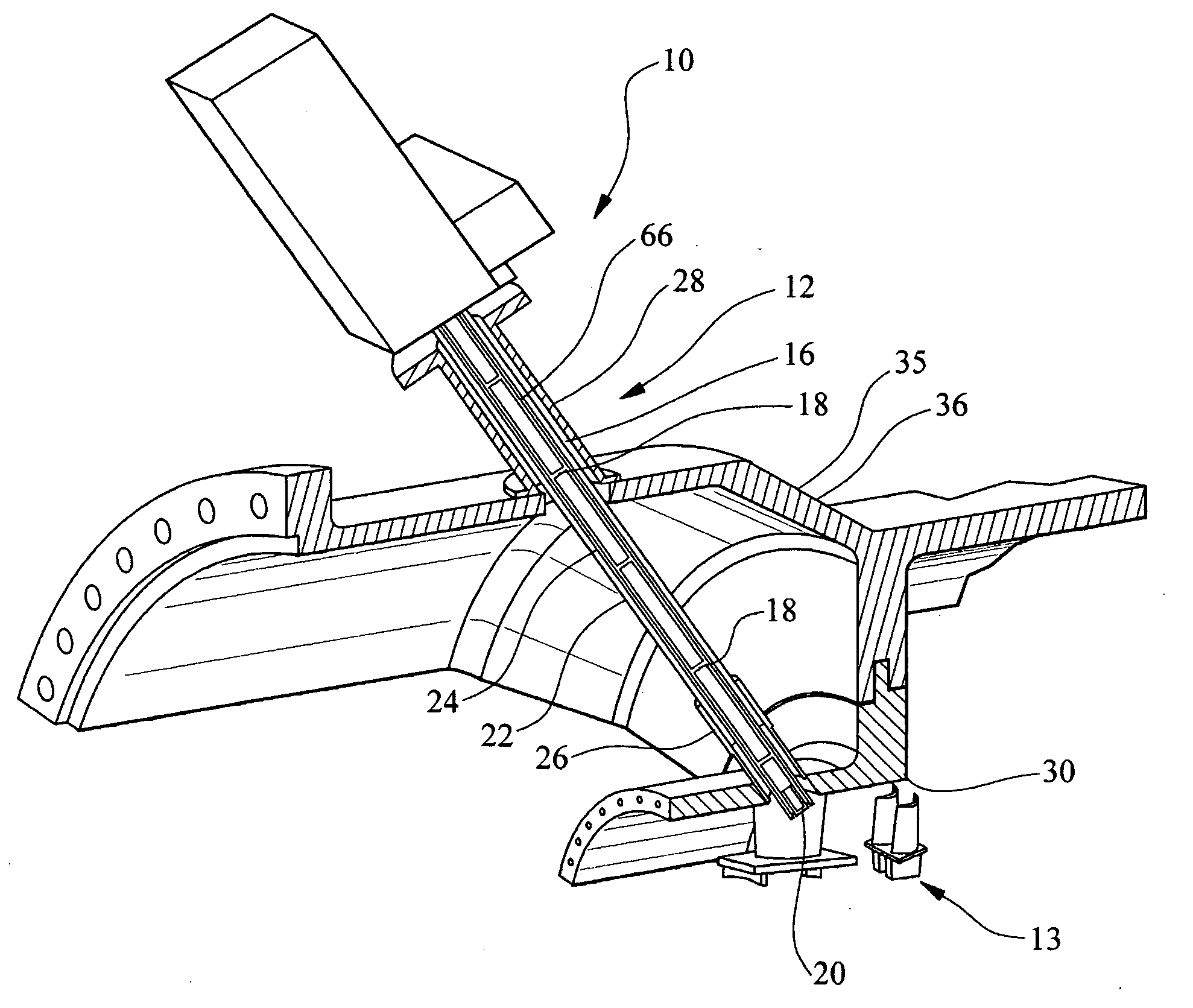
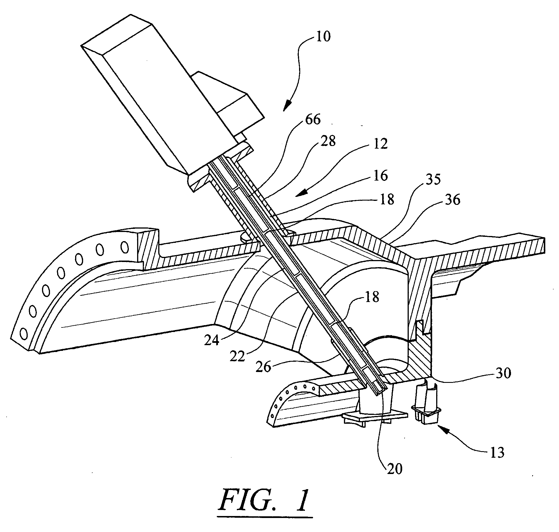
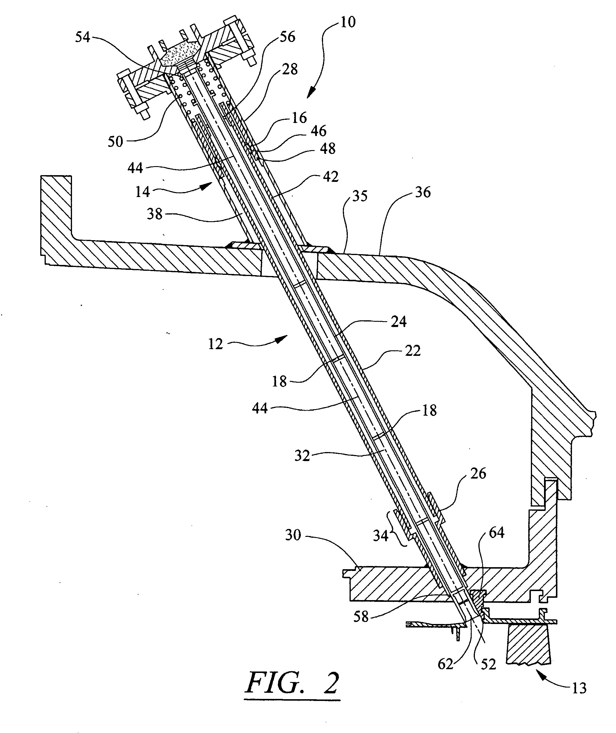
[0015] As shown in FIGS. 1-3, this invention is directed to an inspection system 10 for a turbine engine. The inspection system 10 may be formed from a viewing tube 12 enabling turbine components, such as a turbine blade assembly 13, to be viewed while a turbine engine is operating. In at least one embodiment, the inspection system 10 may be used to visually inspect row one turbine blades or other rows in a turbine engine. The inspection system 10 may include a support system 14 including at least one bearing 16 for supporting the viewing tube 12 while enabling the viewing tube 12 to move relative to the turbine engine to protect the viewing tube 12 from destructive forces developed in a turbine engine during operation. The inspection system 10 may also include one or more lenses 18 positioned inside the viewing tube 12 for enhancing the view through the viewing tube 12. The lenses 18 may be exposed to combustion gases during normal turbine engine operation. During operation, the in...


PUM


Abstract

An inspection system formed at least from a viewing tube for inspecting aspects of a turbine engine during operation of the turbine engine. An outer housing of the viewing tube may be positioned within a turbine engine using at least one bearing configured to fit into an indentation of a support housing to form a ball and socket joint enabling the viewing tube to move during operation as a result of vibrations and other movements. The viewing tube may also include one or more lenses positioned within the viewing tube for viewing the turbine components. The lenses may be kept free of contamination by maintaining a higher pressure in the viewing tube than a pressure outside of the viewing tube and enabling gases to pass through an aperture in a cap at a viewing end of the viewing tube.

Description

FIELD OF THE INVENTION [0001] This invention is directed generally to turbine engines, and more particularly to inspection systems of turbine blade assemblies in turbine engines. BACKGROUND [0002] Typically, gas turbine engines include a compressor for compressing air, a combustor for mixing the compressed air with fuel and igniting the mixture, and a turbine blade assembly for producing power. Combustors often operate at high temperatures that may exceed 2,500 degrees Fahrenheit. Typical turbine combustor configurations expose turbine blade assemblies to these high temperatures. As a result, turbine blades must be made of materials capable of withstanding such high temperatures. [0003] Because of the high temperatures to which turbine blades are often exposed, systems have been developed to monitor various components of a turbine engine during testing to determine the feasibility of the components and operation phenomena. One such system that has been developed is a viewing tube th...

Claims


Application Information

Patent Timeline
Patent Type & Authority Applications(United States)
IPC IPC(8): G01M15/00
CPCF01D21/003G01M15/10F05D2260/80
Inventor SMED, JAN P.LEMIEUX, DENNIS H.WILLIAMS, JAMES P.
Owner SIEMENS ENERGY INC
Why Eureka
Try Eureka