Seat headrest

a headrest and seat technology, applied in the field of seats, can solve the problems of more complicated design of headrests, and achieve the effect of convenient installation and low production cos

Inactive Publication Date: 2007-05-17
REINHOLD IND
View PDF10 Cites 35 Cited by
  • Summary
  • Abstract
  • Description
  • Claims
  • Application Information

AI Technical Summary

Benefits of technology

[0015] Another object of the invention is to provide a headrest construction of the class describe

Problems solved by technology

These types of headrests are of a more complicated de

Method used


Image

  • Seat headrest
  • Seat headrest
  • Seat headrest

Examples


Embodiment Construction

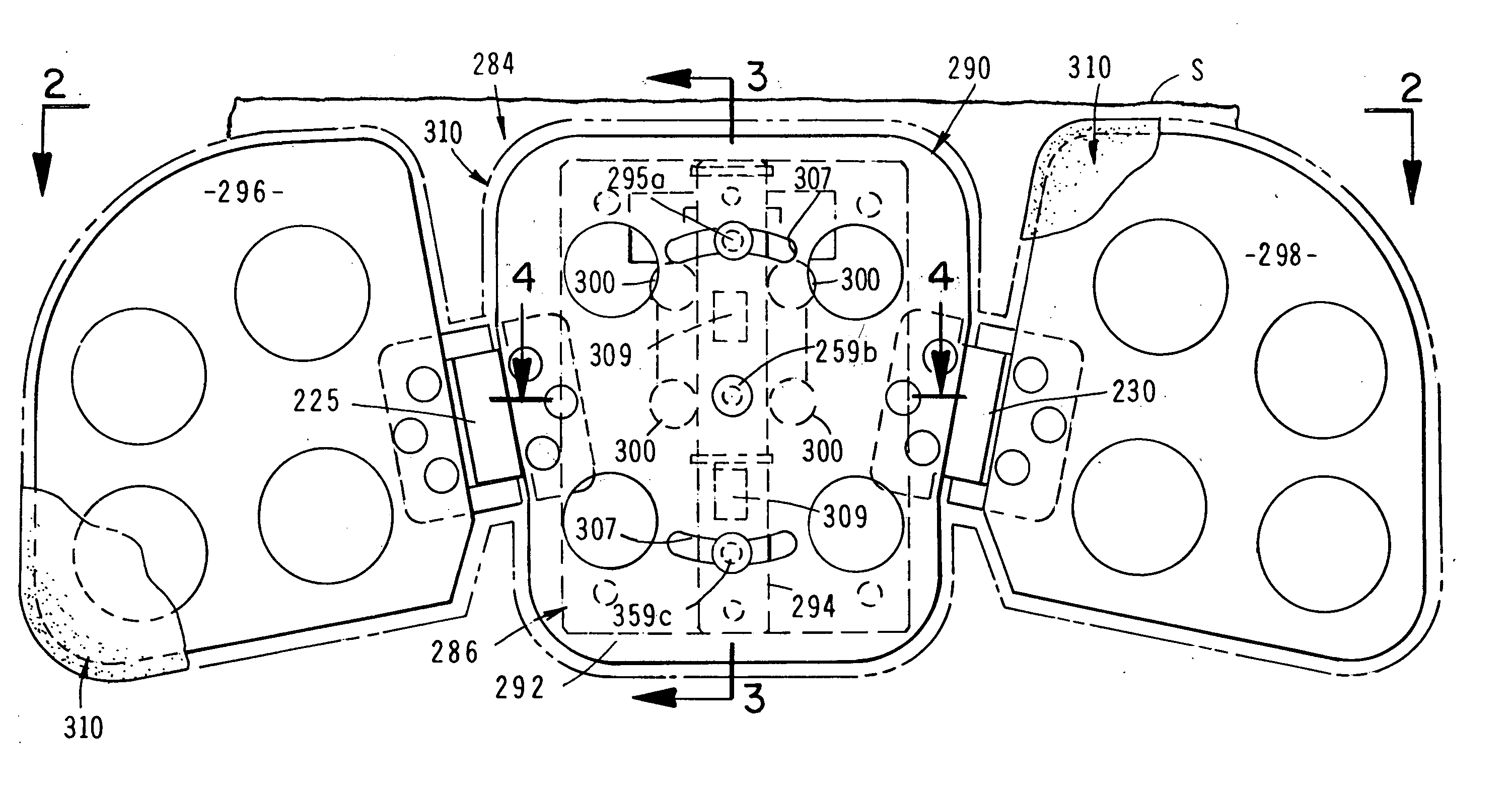
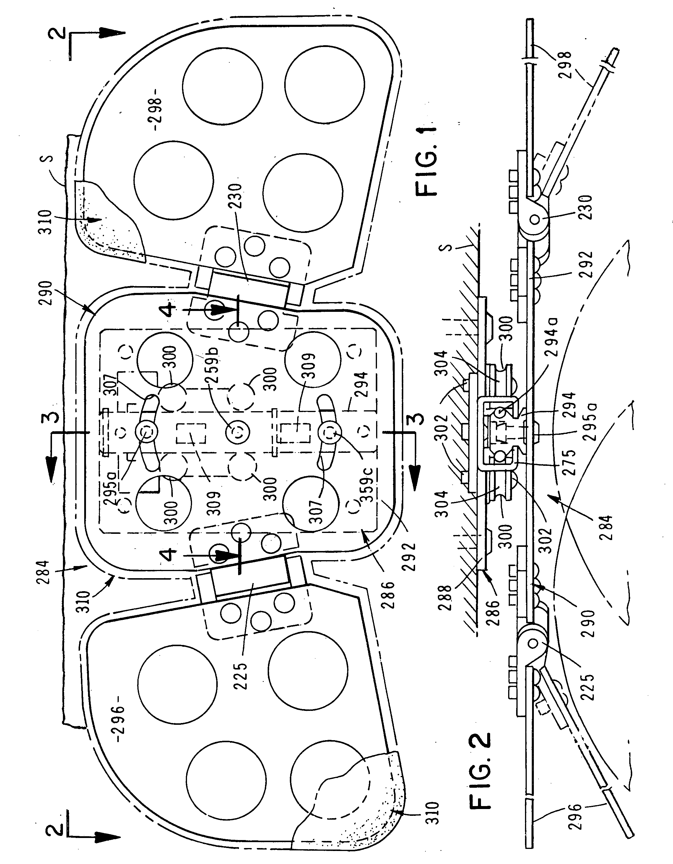
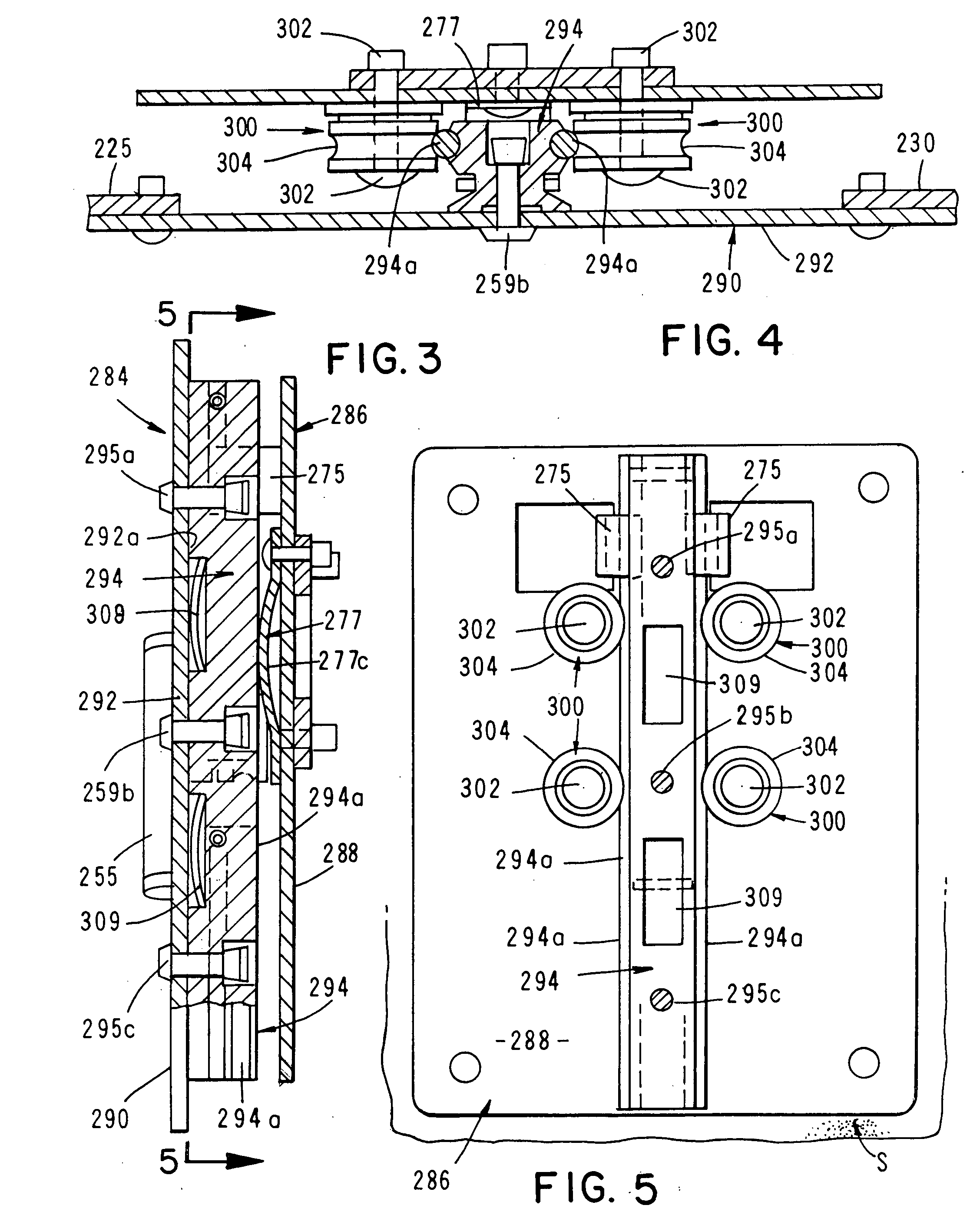
[0045] Referring to the drawings and particularly to FIGS. 1 through 9, one form of seat headrest of the invention is there illustrated and generally designated by the numeral 284. The seat headrest here comprises a generally planar first connector member 288 that is connected to the seat of the vehicle by any suitable means. A head support, or headrest assembly 290 is slidably connected to first connector member 288 for movement between a first lowered position shown in FIG. 1 and an upraised position shown in FIG. 9. As illustrated in FIG. 2, connector member 288 is disposed within a first plane generally parallel with the front surface of seat “S”. As best seen in FIGS. 1 and 2, headrest assembly 290 includes a generally planar central support member or panel 292 to which an elongated guide member 294 is connected by means of connectors 295a, 295b and 295c (FIG. 1). As also illustrated in FIG. 2 support member 292 is disposed in a second plane generally parallel to the first plan...


PUM


Abstract

An adjustable headrest for use with furniture and vehicle seats that includes novel slide mechanisms for permitting easy vertical and horizontal adjustments of the headrest relative to the seat. The headrest also includes wing-like side support members that are pivotally connected to horizontally adjustable slide mechanisms by constant torque hinges. Additionally, the headrest includes a mechanism for permitting pivotal movement of the entire headrest relative to the seat connector which connects the headrest to the seat.

Description

[0001] This is a Continuation-In-Part application of co-pending application Ser. No. 10 / 856,232 filed May 27, 2004 which is a Continuation-In-Part application of application Ser. No. 10 / 744,808, filed Dec. 22, 2003 now U.S. Pat. No. 7,040,705, which is a Continuation-In-Part application of application Ser. No. 10 / 172,477, filed Jun. 14, 2002, now U.S. Pat. No. 6,666,517, which is a Continuation-In-Part application of application Ser. No. 09 / 886,924, filed Jun. 20, 2001, now U.S. Pat. No. 6,467,846, which is a Continuation-In-Part of application Ser. No. 09 / 665,992, filed Sep. 20, 2000, now U.S. Pat. No. 6,250,716.BACKGROUND OF THE INVENTION [0002] 1. Field of the Invention [0003] The present invention relates generally to headrests for seats. More particularly, the invention concerns a fully adjustable headrest for use in connection with furniture and with passenger vehicles such as aircraft, trains and busses. [0004] 2. Discussion of the Prior Art [0005] Various types of headrests ...

Claims


Application Information

Patent Timeline
IPC IPC(8): A47C7/36A47C7/38A47C16/00B60N2/48
CPCB60N2/885A47C7/38A47C7/383
Inventor CLOUGH, ROBERT
Owner REINHOLD IND
Why Eureka
Try Eureka