Plasma display panel (PDP) and plasma display apparatus including the PDP

a plasma display and plasma technology, applied in the direction of gas-filled discharge tubes, gas discharge sealing, electrodes, etc., can solve the problems of deterioration of phosphor substances, excessive production of charged particles in discharge spaces, heavy glass substrate, etc., and achieve the effect of reducing cost and weigh

Inactive Publication Date: 2007-05-17
SAMSUNG SDI CO LTD
View PDF6 Cites 13 Cited by
  • Summary
  • Abstract
  • Description
  • Claims
  • Application Information

AI Technical Summary

Benefits of technology

[0009] The present embodiments provide a plasma display panel (PDP) having a reduced cost and weight.
[0010] The present embodiments also provide a PDP for preventing a temperature of the PDP from increasing.
[0011] The present embodiments also provide a PDP having a simple manufacturing process.
[0012] The present embodiments also provide a PDP for improving a discharge area and brightness.

Problems solved by technology

The glass substrate is heavy and expensive.
Also, the PDP 100 has high temperature discharge spaces due to a high voltage, so that charged particles are excessively produced in the discharge spaces.
The charged particles collide with a phosphor substance, resulting in a deterioration of the phosphor substance and causing an afterimage on a screen.
However, the glass materials used to form the front substrate 101 do not have a good thermal conductivity, thus causing afterimages on the screen.

Method used


Image

  • Plasma display panel (PDP) and plasma display apparatus including the PDP
  • Plasma display panel (PDP) and plasma display apparatus including the PDP
  • Plasma display panel (PDP) and plasma display apparatus including the PDP

Examples


Embodiment Construction

[0046] The present embodiments will now be described more fully with reference to the accompanying drawings, in which exemplary embodiments are shown.

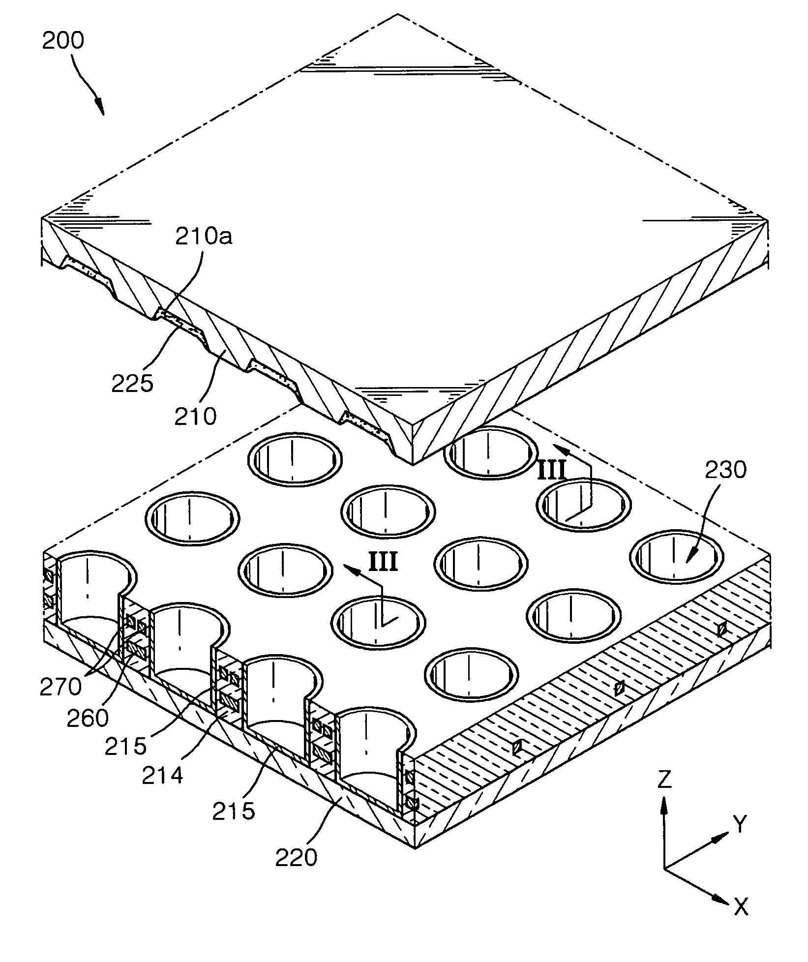
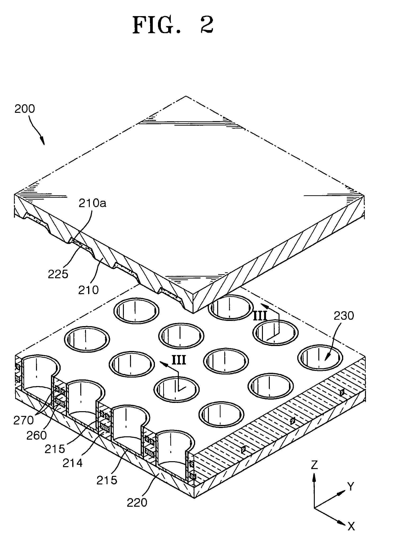
[0047]FIG. 2 is a partially exploded perspective view of a PDP 200 according to an embodiment. FIG. 3 is a cross-sectional view of the PDP of FIG. 2 taken along a line III-III in FIG. 2 according to an embodiment. FIG. 4 schematically illustrates discharge cells 230 and first and second discharge electrodes 260 and 270 illustrated in FIG. 2 according to an embodiment.

[0048] Referring to FIGS. 2 and 3, the PDP 200 comprises a transparent substrate 210, a sealing member 220, electrode buried walls 214, pairs of discharge electrodes 260 and 270, and phosphor layers 225.

[0049] Visible light for displaying an image is transmitted through the transparent substrate 210. Therefore, the transparent substrate 210 is formed of a high transparent material such as glass. The transparent substrate 210 can be colored in order to increase a bright ...


PUM


Abstract

A plasma display panel (PDP) that improves a transmittance rate of visible rays, prevents address electrodes from producing a lot of heat, and reduces the occurrence of afterimages from the PDP, and a plasma display apparatus using the PDP are provided. The PDP includes: a substrate through which visible rays displaying an image are transmitted; a plurality of electrode buried walls arranged below the substrate and defining discharge cells; a plurality of pairs of discharge electrodes spaced apart from each other in the electrode buried walls and performing a discharge in the discharge cells; a sealing member arranged below the electrode buried walls, sealing a discharge gas together with the substrate, and formed of a material having a higher thermal conductivity than that of the substrate; and phosphor layers arranged in the discharge cells.

Description

CROSS-REFERENCE TO RELATED PATENT APPLICATION [0001] This application claims the benefits of Korean Patent Application No. 10-2005-0108297, filed on Nov. 12, 2005, in the Korean Intellectual Property Office, the disclosure of which is incorporated herein in its entirety by reference. BACKGROUND OF THE INVENTION [0002] 1. Field of the Invention [0003] The present embodiments relate to a plasma display panel (PDP) and a plasma display apparatus including the PDP, more particularly, to a PDP that displays an image using a plasma discharge and a plasma display apparatus including the PDP. [0004] 2. Description of the Related Art [0005] Plasma display panels (PDP) which have replaced conventional cathode ray tube (CRT) display devices display desired images using visible rays generated by sealing discharge gas and applying discharge voltage between two substrates on which a plurality of electrodes are formed to generate vacuum ultraviolet rays and exciting phosphor on which the vacuum ul...

Claims


Application Information

Patent Timeline
Patent Type & Authority Applications(United States)
IPC IPC(8): H01J17/49H01J11/14H01J11/16H01J11/22H01J11/24H01J11/26H01J11/32H01J11/34H01J11/36H01J17/16
CPCH01J11/16H01J11/48H01J2211/366H01J2211/38H01J11/22
Inventor KANG, KYOUNG-DOOYI, WON-JUAHN, HO-YOUNGLEE, DONG-YOUNGPARK, SOO-HOWOO, SEOK-GYUNKWON, JAE-IK
Owner SAMSUNG SDI CO LTD
Why Eureka
Try Eureka