Rotation angle detection device

Inactive Publication Date: 2007-05-17
MITSUBA CORP
View PDF3 Cites 10 Cited by
  • Summary
  • Abstract
  • Description
  • Claims
  • Application Information

AI Technical Summary

Benefits of technology

[0037] According to the rotation angle detection device of the present invention, the magnet is disposed with a predetermined space apart from the yoke member formed of a magnetic material rotating in synchronization with the rotary shaft in the axial direction, and the magnetic detection element is disposed in the magnetic path formed by the magnet. Accordingly, opposed surfaces between the yoke member and magnet extend in the radial direction to reduce the axial direction length of the device. Therefore, the thickness of the rotation angle detection device can be reduced to thereby increase the layout flexibility of the device.
[0038] Further, according to the rotation angle detection device of the present invention, the yoke member formed of a magnetic material is disposed with a predetermined space apart from the magnet rotating in synchronization with the rotary shaft in the axial direction, and the magnetic detection element

Problems solved by technology

However, in the rotation angle detection device having the configuration as shown in FIG. 13, output characteristics are structurally vulnerable to center displacement.
This makes a change in the amount of the flux passing through the Hall IC 56 non-uniform with respect to the rotation angle, resulting in detection error.
While it is possibl

Method used


Image

  • Rotation angle detection device
  • Rotation angle detection device
  • Rotation angle detection device

Examples


first embodiment

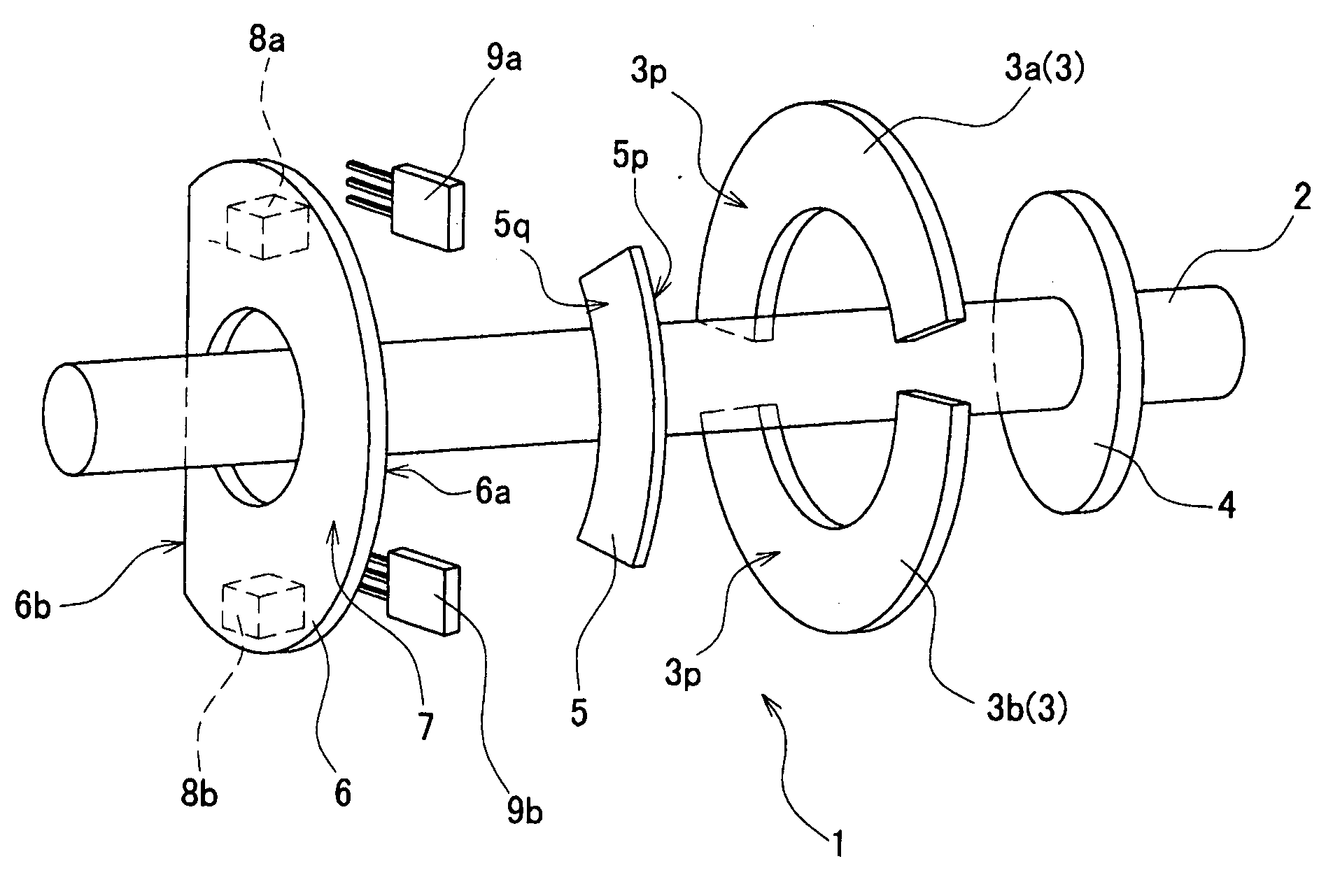
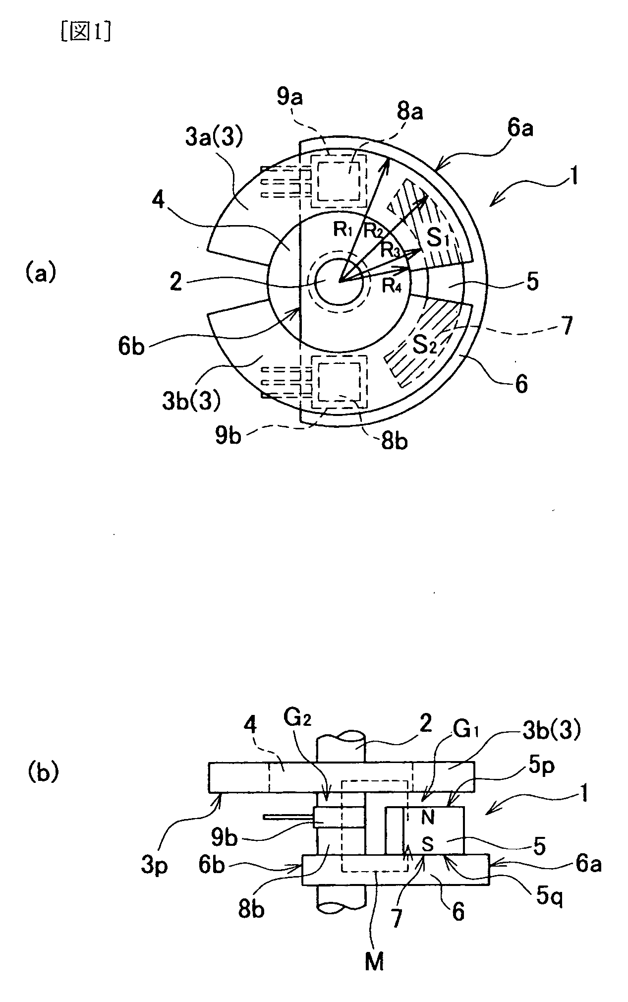
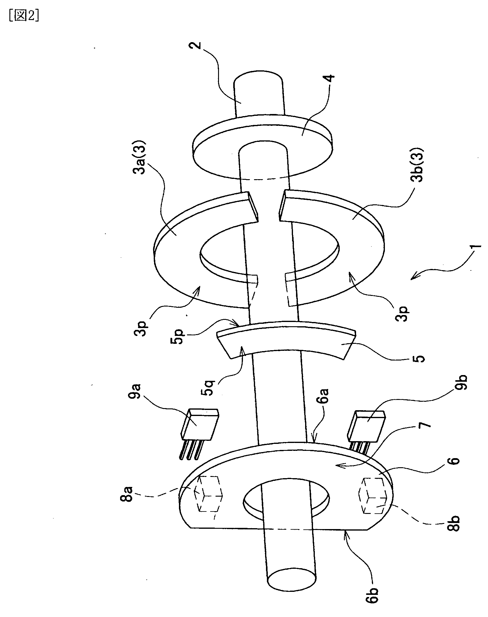
[0108]FIG. 1 is explanatory views showing a configuration of a rotation angle detection device according to a first embodiment of the present invention. FIG. 1 (a) is a front view of the rotation angle detection device, and FIG. 1 (b) is a bottom view thereof. FIG. 2 is an exploded perspective view of the rotation angle detection device of FIG. 1. As shown in FIG. 1, yoke plates (yoke members) 3a, 3b rotating in synchronization with a rotary shaft 2 are provided in a rotation angle detection device 1. Each of the yoke plates 3a, 3b is formed of a magnetic material and formed in a partially cylindrical shape having a central angle of about 160°. The yoke plates 3a, 3b are circumferentially fixed to the rotary shaft 2 through a rotor core 4 of nonmagnetic material in even shares.

[0109] A magnet 5 having a sector shape is disposed on the axial direction edge surface 3p side of the yoke plates 3a, 3b with a predetermined space apart from the yoke plates 3a, 3b. The magnet 5 is fixed to...

second embodiment

[0117]FIG. 3 is explanatory views showing a configuration of a rotation angle detection device according to a second embodiment of the present invention. FIG. 3 (a) is a front view of the rotation angle detection device, and FIG. 3 (b) is a bottom view thereof. In the following embodiments, the same reference numerals as the first embodiment are given to the components which are common to the first embodiment, and the overlapped description is omitted.

[0118] As shown in FIG. 3, two magnets 5 (5a, 5b) are provided in a rotation angle detection device 10 according to the second embodiment. The magnets 5a, 5b are so magnetized as to have magnetic poles of different polarities alternately arranged in the rotational direction. The fixing plate 6 is formed not into a semilunar shape, but into a circular shape for placement of the two magnets. In this configuration, as shown in FIG. 3(b), two separate magnetic paths M1, M2 are formed by the magnets 5a, 5b. That is, the magnetic paths M1, ...

third embodiment

[0120]FIG. 4 is a cross-sectional view showing a configuration of an electronically-controlled throttle valve using a rotation angle detection device according to a third embodiment. FIG. 5 is a bottom view of the electronically-controlled throttle valve of FIG. 4. The electronically-controlled throttle valve shown in FIGS. 4 and 5 is disposed in the inlet path of an engine. Intake air flow of the engine is controlled by the open degree of the throttle valve 11. The throttle valve 11 is fixed to the valve shaft (rotary shaft) 12 and driven by a brushless motor 13 (hereinafter, abbreviated as motor 13) through a speed-reduction mechanism 25 constituted by gears 21 to 24.

[0121] The valve shaft 12 is pivotably supported by a not shown bearing fixed to a metal housing 14. A plastic cover 15 is attached to the lower portion of the housing 14, as shown in FIG. 4. A circuit board 16 is fixed inside the cover 15. A torsion coil spring is attached to the throttle gear 21 fixed to the valve ...


PUM


Abstract

Yoke plates (3a, 3b) of magnetic material adapted for rotation in synchronism with a rotary shaft (2) are installed. An axially magnetized magnet (5) is disposed through the yoke plates (3a, 3b) and an air gap (G1). The outer diameter (R1) of the yoke plates (3a, 3b) is larger than the outer diameter (R2) of the magnet (5). The magnet (5) is fixed to a fixing plate (6) of magnetic material. Hall ICs (9a, 9b) are attached to the front ends of the pole pieces (8a, 8b) of the fixing plate (6). The Hall ICs (9a, 9b) are disposed in a magnetic circuit (M) formed by the magnet (5). When the rotary shaft (2) rotates, the opposed areas (S1, S2) between the magnet (5) and the yoke plates (3a, 3b) vary, so that the density of magnetic flux passing through the Hall ICs (9a, 9b) in the magnetic circuit (M) linearly varies in proportion to the rotation angle. The Hall ICs (9a, 9b) catch this variation and detect the rotation angle of the rotary shaft (2). Thereby, the cost of production of the rotation angle detection device is reduced without deteriorating the detection accuracy.

Description

TECHNICAL FIELD [0001] The present invention relates to a rotation angle detection device which detects the rotation angle of an object to be detected and, more particularly, to a technique effectively applied to a detection device for detecting the open degree of an engine throttle valve. BACKGROUND ART [0002] There is known, as a non-contact type rotation angle detection device, a configuration as disclosed in, e.g., Japanese Patent No. 2842482, in which a change in flux caused by a magnet attached to an object to be detected is caught to detect the rotation angle of the object. FIG. 13 is an explanatory view showing a general configuration of such a non-contact type rotation detection device. [0003] In a rotation angle detection device of FIG. 13, a rotor core 52 of magnetic material is attached to a shaft 51 which is subject to rotation angle detection. A dipole ring magnet 53 is fixed to the inner circumference of the rotor core 52. A stator core 54 is disposed outside the ring...

Claims


Application Information

Patent Timeline
IPC IPC(8): G01B7/30F02D9/10G01D5/14
CPCF02D9/105G01D5/145G01D5/147
Inventor OOTAWARA, MASAHIROKAWAMURA, MIKIONEGISHI, SATORUTAKAKUSAGI, RYUICHI
Owner MITSUBA CORP
Why Eureka
Try Eureka