
Electronic judging apparatus for working state of the equipment

a technology of electronic equipment and working state, applied in the field of electronic equipment, can solve the problems that the remodeling of the interface circuit of the electric equipment used in the ordinary family house is difficult to be applied to the ordinary user's electric equipment, and the conventional methods are not applicable to the equipment used in the ordinary family house, so as to reduce the noise of the equipment and the effect of reducing the cos

Inactive Publication Date: 2007-05-17
KONNO AKIRA
View PDF8 Cites 13 Cited by
  • Summary
  • Abstract
  • Description
  • Claims
  • Application Information

AI Technical Summary

Benefits of technology

[0027] Accordingly, the object of the present invention is to offer an electronic apparatus with automatic judging function for the working state of the other equipment, which can be used without modifying the equipment and easily used by the ordinary user without the knowledge of the special electronic circuit.
[0037] The noises caused by the electronic equipments are separated into two categories of normal mode noise and common mode noise. Though the reduction of the normal mode noise inside the electronic equipment is relatively easier, the reduction of the common mode noise is restricted by the following reason.
[0055] On the other hand, an electric heater and an incandescent lamp are hard to be judged by the apparatus of the present invention, because the common mode noise can be less detected.
[0057] As the electric contact to the circuit of the equipment to be judged is not necessary for applying the present invention, the safe installation can be done with cheaper cost.
[0058] Furthermore, as the judging equipment with the detector of the present invention can work as the LFT itself, it also works to decrease the noise of the equipment to be judged.

Problems solved by technology

However, the conventional methods for detecting the working state of the equipment require the installation of the interface circuit in the equipment itself.
In another words, these conventional methods are not applicable onto the equipment used in the ordinary family house after purchase from the equipment store.
Especially, the electric equipment as television set, microwave oven, toaster or washing machine are difficult to be applied the remodeling of the interface circuit for the ordinary users.

Method used


Image

  • Electronic judging apparatus for working state of the equipment
  • Electronic judging apparatus for working state of the equipment
  • Electronic judging apparatus for working state of the equipment

Examples


Embodiment Construction

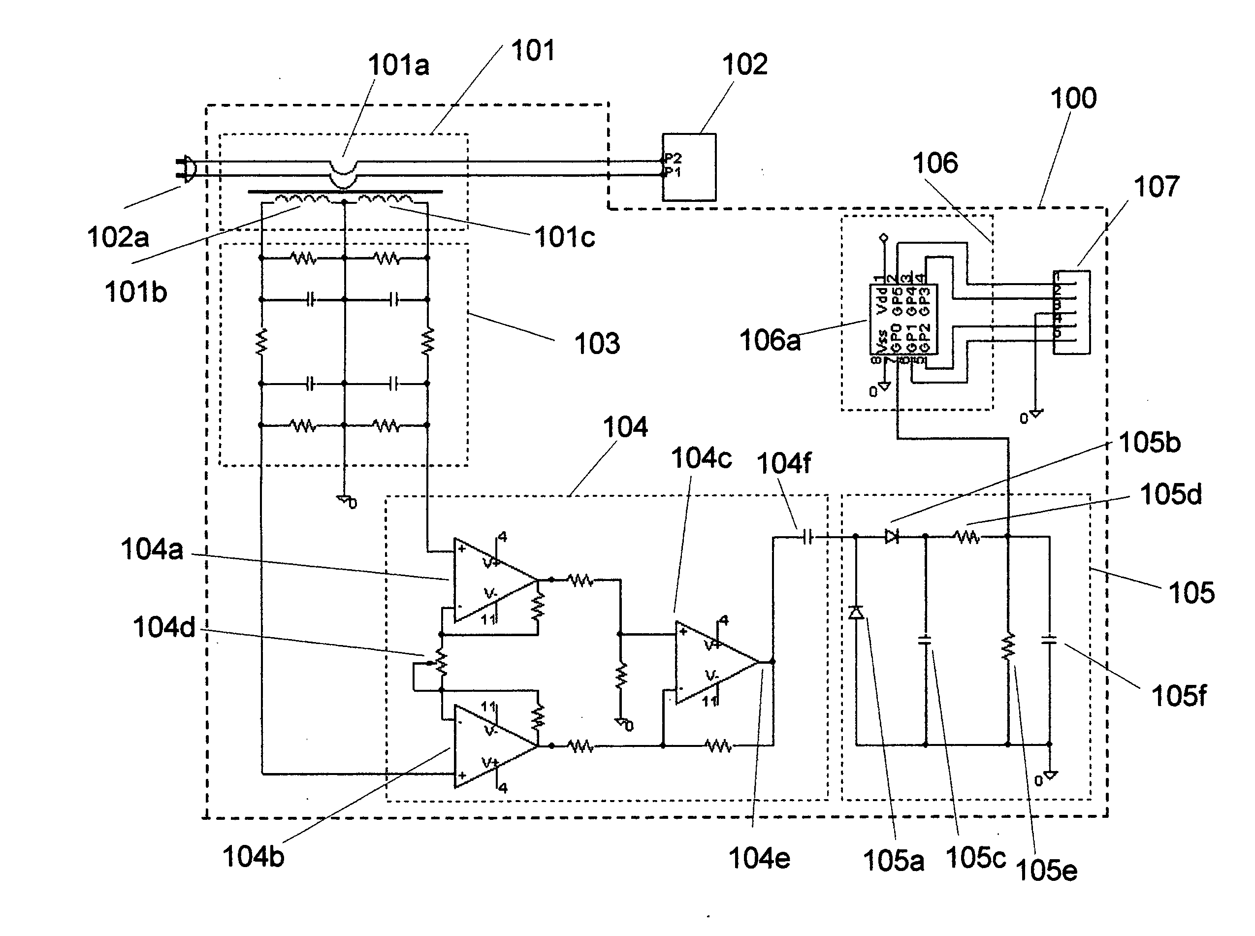
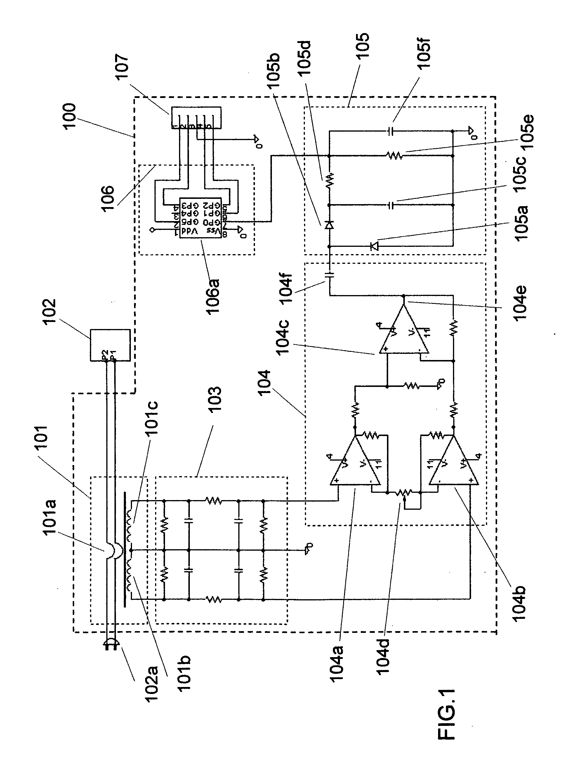
[0066] Hereinafter, the preferred embodiments of the present invention are described precisely by using the figures. For example, the electronic judging apparatus for the working state of the other equipment is actualized by using the electronic circuit 100 as shown in FIG. 1.

[0067] It is understood that the circuit of FIG. 1 is constructed mainly from the five block portions with each function of the circuit unit. As surrounded by each broken line, the five portions are composed of the detecting function block 101, the filter function block 103, the differential amplifying function block 104, integration circuit block with rectification 105 and AD converting circuit block with digital signal treatment 106.

[0068] The signal output interface 107 is situated between the AD converting circuit block 106 and the outer connection to send the output. The other electronic equipment 102 to be judged the working state has paired electric wires for power supplying and is connected with the p...


PUM


Abstract

The invention provides the electronic judging apparatus to detect the working state of the other electric equipment without modifying it inside. The common mode noise around the electric power supplying wires of the other equipment is measured by using the special magnetic core detector attached around the power supplying wire, and the common mode noise is compared with the one measured on the non-working time after amplifying and digital signal treatment of the detected signal. As the modification of the equipment is not required, the monitoring of the working state can be available for various equipments easily and also available from a remote place by transmitting the digital treated signal on the internet communication system.

Description

BACKGROUND OF THE INVENTION [0001] 1. Field of the Invention [0002] The present invention relates to an electronic apparatus with automatic judging function for the working state of the other equipment. [0003] 2. Description of Related Art [0004] Conventional example of the electronic judging method for the working state of the other equipment is presented in Japanese Patent Application Laid-Open No. 1999-55761. Conventional examples for detecting operation state of the related system are presented in U.S. Pat. No. 5,570,418 and U.S. Pat. No. 4,310,844. [0005] The conventional methods of the electronic judging for the working state of the other equipment are explained with the following examples. The first example of them is the method utilizing the electric switch situated common to the operation switch of the other equipment itself. [0006] The second example is the way to use the electric limit switch with mechanical contact movement or semiconductor limit switch with magnetic fie...

Claims


Application Information

Patent Timeline
Patent Type & Authority Applications(United States)
IPC IPC(8): G01R31/28
CPCG01R29/26G01R31/2825
Inventor KONNO, AKIRA
Owner KONNO AKIRA
Learn More