Integrated dielectric resonator filter and clock extraction device using the same

a dielectric resonator and clock extraction technology, applied in the direction of resonators, oscillators, electrical equipment, etc., can solve the problems of increasing signal loss, dielectric resonator filters affecting the use of open-loop clock extraction devices, and difficult integration of conventional disc-type dielectric resonator filters with other electrical circuits

Inactive Publication Date: 2007-05-17
ELECTRONICS & TELECOMM RES INST
View PDF2 Cites 6 Cited by
  • Summary
  • Abstract
  • Description
  • Claims
  • Application Information

AI Technical Summary

Problems solved by technology

Thus, the conventional disc type dielectric resonator filter is difficult to integrate with other electrical circuits, such as nonlinear circuits and clock amplifiers, in a clock extraction device.
Accordingly, conventional dielectric resonator filters hinder open-loop clock extraction devices using dielectric resonator filters from being compact.
As a result, the signal loss increases.
Also, in a case of several Gb / s clock extraction devices using the conventional dielectric resonator filters, a plurality of undesired spurious pass bands exist in the vicinity of central frequencies of the conventional dielectric resonator filters that mean clock frequencies.

Method used


Image

  • Integrated dielectric resonator filter and clock extraction device using the same
  • Integrated dielectric resonator filter and clock extraction device using the same
  • Integrated dielectric resonator filter and clock extraction device using the same

Examples


Embodiment Construction

[0026] Hereinafter, the present invention will be described in detail with reference to the attached drawings.

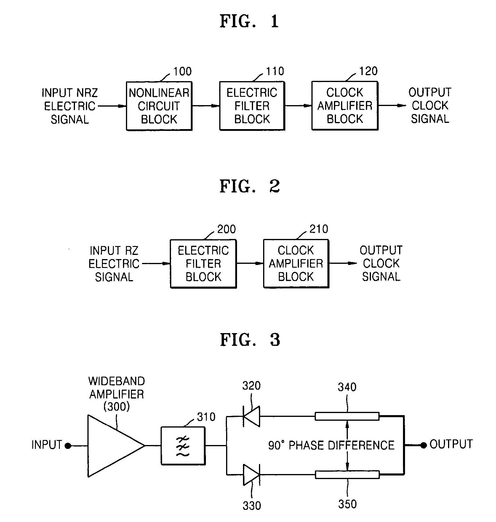
[0027]FIG. 1 is a block diagram of a general open-loop type clock extraction device for extracting a clock signal from an NRZ signal. Referring to FIG. 1, the general open-loop type clock extraction device includes a nonlinear circuit block 100 converting a received NRZ signal into a PRZ signal from which clock information is generated, an electric filter block 110 extracting a clock signal component from the PRZ signal, and a clock amplifier block 120 amplifying the clock signal.

[0028]FIG. 2 is a block diagram of a general open-loop type clock extraction device for extracting a clock signal from an RZ signal. Referring to FIG. 2, the general open-loop type clock extraction device includes an electric filter block 200 and a clock amplifier block 210.

[0029]FIG. 3 is a circuit diagram of a nonlinear circuit unit using a pair of diodes and a power combiner having a phase dif...


PUM


Abstract

Provided are an integrated dielectric resonator filter and a clock extraction device using the integrated dielectric resonator filter. The integrated dielectric resonator filter includes: a microwave substrate; a disc type dielectric resonator installed on the microwave substrate and having predetermined diameter and height; an input and output transmission line installed on both sides of the disc type dielectric resonator to transmit input and output signals; and a metal cover enclosing the disc type dielectric resonator to form a predetermined volume, opened toward the input and output transmission line, and closed in an orthogonal direction to the input and output transmission line.

Description

CROSS-REFERENCE TO RELATED PATENT APPLICATION [0001] This application claims the benefit of Korean Patent Application No. 10-2005-0110182, filed on Nov. 17, 2005, in the Korean Intellectual Property Office, the disclosure of which is incorporated herein in its entirety by reference. BACKGROUND OF THE INVENTION [0002] 1. Field of the Invention [0003] The present invention relates to a dielectric resonator filter adopted in an receiver for the ultrahigh optical transmission system and a clock extraction device using the same, and more particularly, to an electric filter extracting a clock signal from the received data to reproduce a clock signal in an optical receiver and an open-loop type clock extraction device using the same. [0004] 2. Description of the Related Art [0005] Clock extraction devices are slightly differently constituted according to types of used transmission signals. In a case where NRZ signals are used, signals corresponding to clock frequencies do not exist. Thus, ...

Claims


Application Information

Patent Timeline
Patent Type & Authority Applications(United States)
IPC IPC(8): H03B9/14
CPCH01P1/20309H03B9/148H01P1/20H01P7/10H03H9/00
Inventor LIM, SANG KYULEE, SANG SOOCHO, HYUN WOOKO, JE SOO
Owner ELECTRONICS & TELECOMM RES INST
Why Eureka
Try Eureka