Antenna capable of producing radio frequency orbital angular momentum beams based on dielectric resonator

A technology of dielectric resonator and orbital angular momentum, which is applied in the direction of antenna, antenna array, antenna grounding switch structure connection, etc., can solve the problems of limiting the promotion and application of orbital angular momentum communication, increasing cost and power consumption, and difficult system integration. Achieve the effects of promoting research and application, reducing power consumption and cost, and increasing transmission rate

Active Publication Date: 2015-09-30
ZHEJIANG UNIV
View PDF4 Cites 7 Cited by
  • Summary
  • Abstract
  • Description
  • Claims
  • Application Information

AI Technical Summary

Problems solved by technology

However, most of the existing generation and emission devices have shortcomings such as large size and difficulty in integrating with existing systems.
Large size will increase cost and power consumption, and it is not suitable for integration with existing systems, thus limiting the promotion and application of this emerging technology of orbital angular momentum communication

Method used


Image

  • Antenna capable of producing radio frequency orbital angular momentum beams based on dielectric resonator
  • Antenna capable of producing radio frequency orbital angular momentum beams based on dielectric resonator
  • Antenna capable of producing radio frequency orbital angular momentum beams based on dielectric resonator

Examples


Embodiment 1

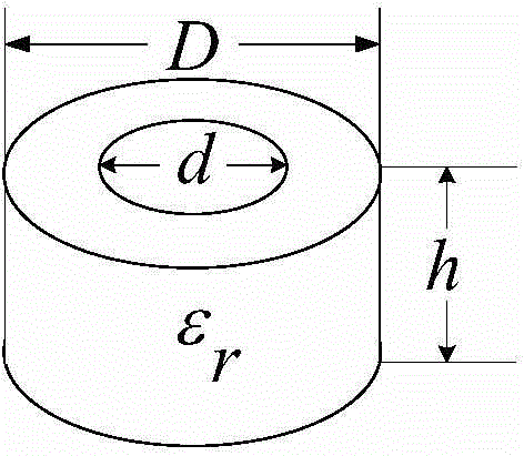
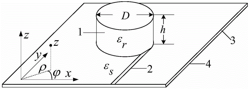
[0033]The specific parameters used in this example are D=12mm, d=0mm, h=5mm,ε r =12,ε s =3.66, the microstrip line is a 50 ohm microstrip line, and the radiation frequency is 15GHz-25GHz. By choosing different frequencies, radio frequency orbital angular momentum beams with different orders can be launched.

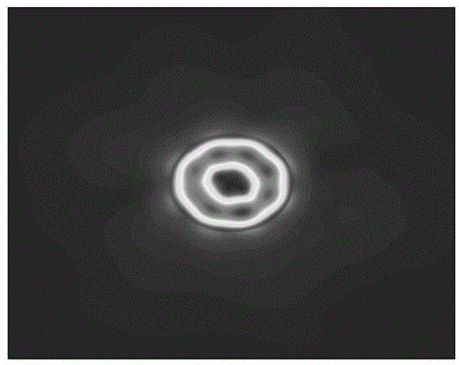
[0034] image 3 It is the electric field distribution diagram inside and around the dielectric resonator obtained by using the electromagnetic simulation software CST simulation, and the resonance frequency is 20.38GHz. From image 3 It can be seen that the electric field is mainly concentrated at the boundary between the dielectric resonator and free space and its vicinity, and there is no electromagnetic field distribution in the central region of the dielectric resonator, which is a typical electric field distribution characteristic of the orbital angular momentum beam. Figure 4 It is the phase distribution diagram of the z-direction electric field. It can be seen...


PUM


Abstract

The invention discloses an antenna capable of producing radio frequency orbital angular momentum beams based on a dielectric resonator. The antenna comprises a microwave dielectric resonator, a microstrip line, a microwave substrate and a metal ground plane, wherein the microwave dielectric resonator adopts a cylindrical structure and has an annular cross section, the external diameter is D, the internal diameter is d, the height is h, and d is larger than or equal to 0 and smaller than D; the relative dielectric constant of the microwave dielectric resonator is epsilon r, the microwave dielectric resonator is placed on the microwave substrate with the relative dielectric constant being epsilon s, the metal ground plane is arranged below the microwave substrate, the microwave dielectric resonator performs feeding through the microstrip line, and a whispering-gallery mode in the dielectric resonator is excited. The dielectric resonator with simple structure is designed and used to realize emission of radio frequency beams carrying different l-order orbital angular momentum at different direction angles, and the antenna has quite important meaning for the emerging fields of high-speed radio frequency communication, radar detection and the like by using the orbital angular momentum.

Description

technical field [0001] The invention belongs to the technical field of radio frequency orbital angular momentum wireless communication, and relates to an antenna for generating radio frequency orbital angular momentum beams based on a dielectric resonator. Background technique [0002] With the development of mobile communication technologies such as smart phones, people's requirements for wireless communication rates are also getting higher and higher. However, spectrum resources are in short supply, and the spectrum available for use has become less and less. The traditional method of increasing the communication rate by dividing new communication frequency bands has become unsustainable. How to improve the wireless communication rate under limited communication resources is an important issue in the communication industry. a great challenge. At present, multiplexing technologies such as time-division multiplexing, frequency-division multiplexing, and code-division multip...

Claims


Application Information

Patent Timeline
Patent Type & Authority Applications(China)
IPC IPC(8): H01Q1/36H01Q1/50H01Q21/00
Inventor 潘毓郑史烈章献民
Owner ZHEJIANG UNIV
Why Eureka
Try Eureka