Multi-band antenna

Active Publication Date: 2012-07-12
AUDEN TECHNO
View PDF6 Cites 7 Cited by
  • Summary
  • Abstract
  • Description
  • Claims
  • Application Information

AI Technical Summary

Benefits of technology

[0009]The object of the instant disclosure is to provide a multi-band antenna, which has multiple operating bandwidths and covers bandwidths from low-frequency to high-frequency Particularly, the instant disclosure provides a multi-band antenna, which includes a microwave substrate, a first antenna unit, a second antenna unit, a third antenna unit and a grounding unit. The first antenna unit, the second antenn

Problems solved by technology

Multi-band antenna designs encounter a technical challenge of antenna size miniaturization because the negative effects of coupling interference between nearby antenna components may become more influential as the antenna's physical dimensions are reduced.
The coupling interference between each component on a miniature multi-band antenna in close proximity may cause serious of impedance bandwidth, antenna ga

Method used


Image

  • Multi-band antenna
  • Multi-band antenna
  • Multi-band antenna

Examples


first embodiment

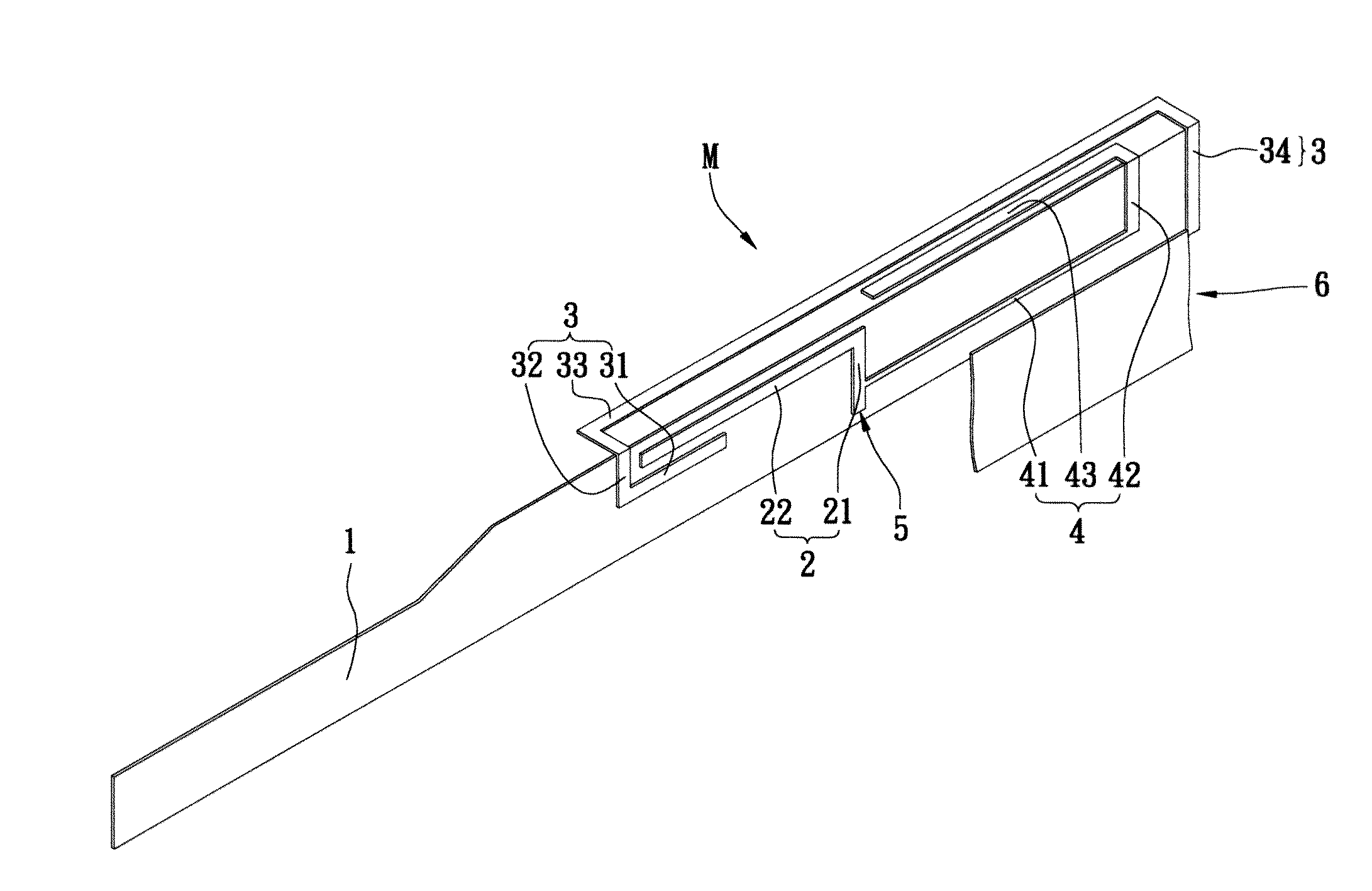
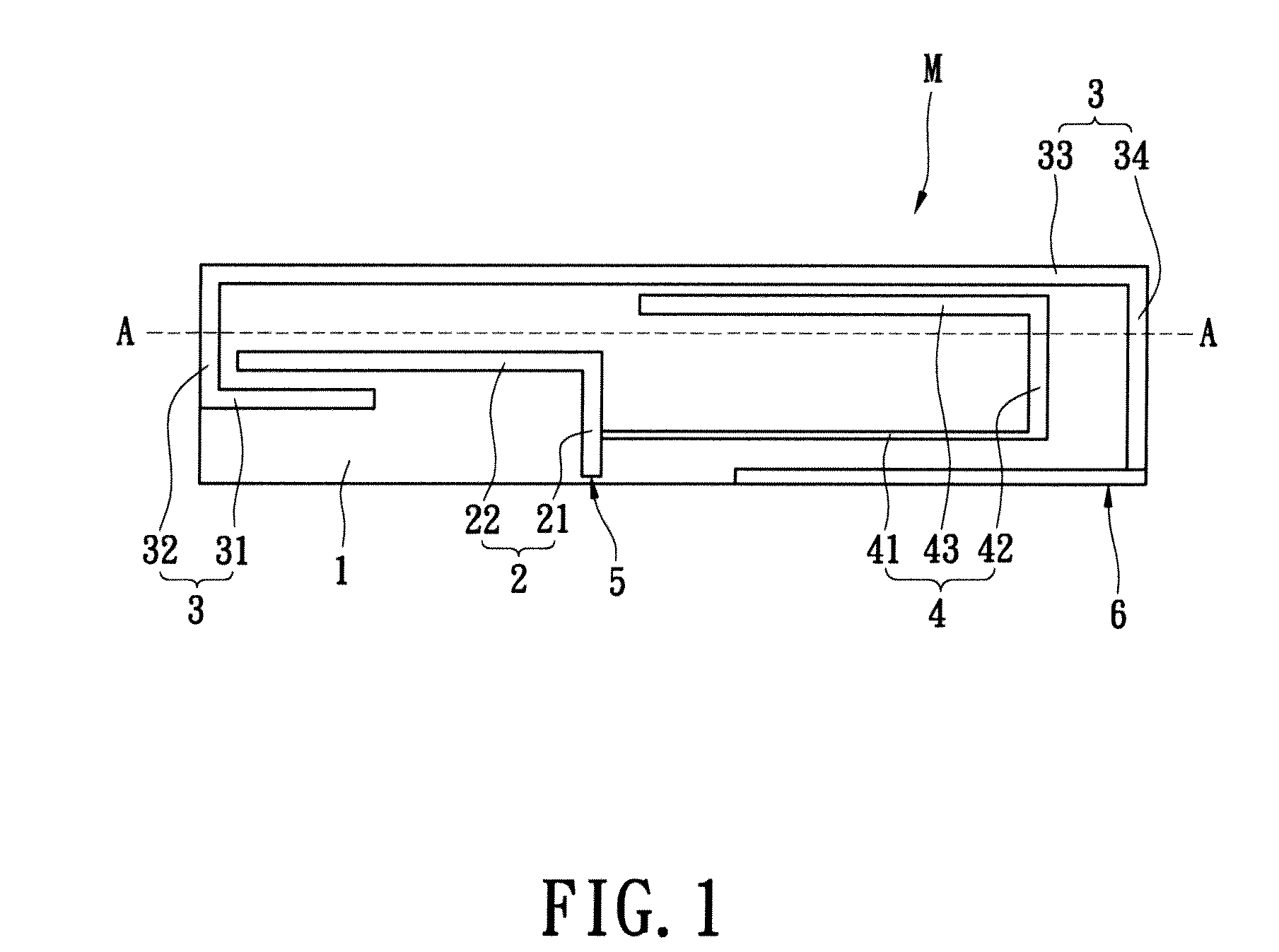
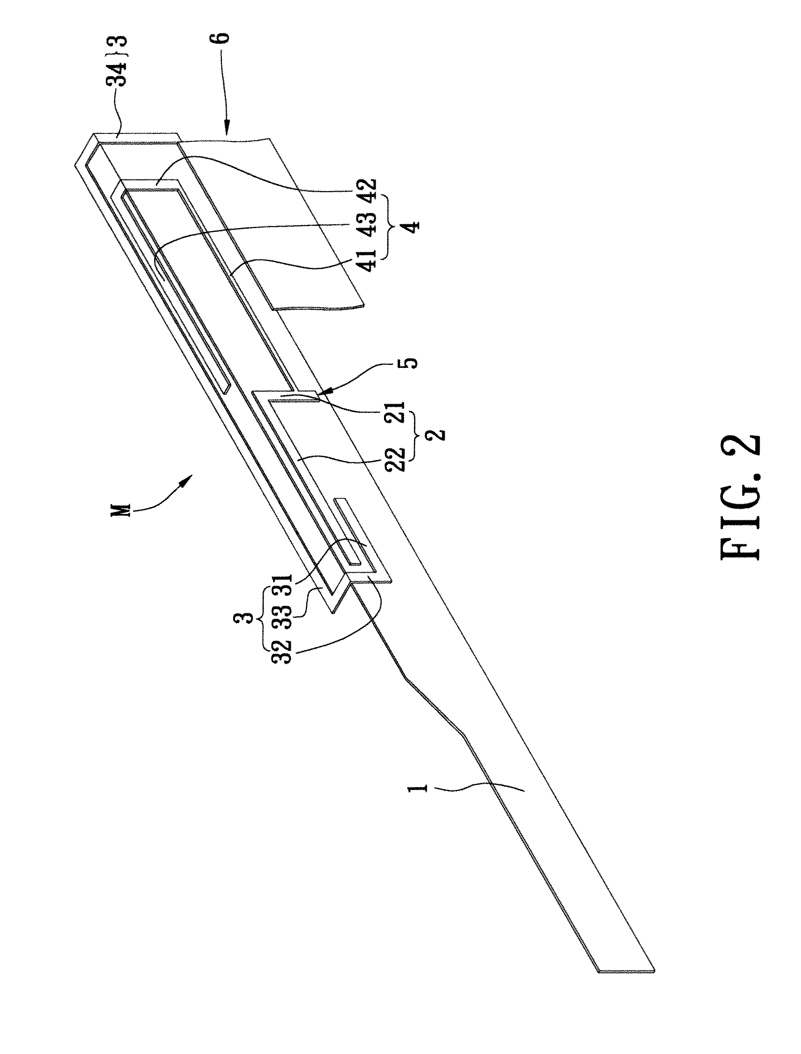
[0018]Please refer to FIG. 1 and FIG. 2, which show the configurations of the instant disclosure for a multi-band antenna M. The multi-band antenna M includes a microwave substrate 1, a first antenna unit 2, a second antenna unit 3, a third antenna unit 4 and a grounding unit 6.

[0019]The first antenna unit 2 includes a first extended segment 21 and a first distal segment 22. The first distal segment 22 is connected to the terminal portion of the first extended segment 21. The first distal segment 22 is perpendicular to the first extended segment 21. The feeding point 5 of the first antenna unit 2 can be connected to a 50 Ω coaxial cable.

[0020]The second antenna unit 3 includes a second extended segment 31, a second bent segment 32, a second straight segment 33, and a second distal segment 34. The second bent segment 32 is connected to the terminal portion of the second extended segment 31. The second bent segment 32 is perpendicular to the second extended segment 31, and the second ...

second embodiment

[0029]In the second embodiment, the width of metallic micro-strip of the second straight segment 33 can be 3 mm. The width of metallic micro-strip of the first section 411, the second section 412, the third section 413, the fourth Section 414, and the fifth section 415 can be 0.3 mm. The width of metallic micro-strip of the third bent segment 42, the sixth section 431, and the seventh section 432 can be 1 mm. The width of metallic micro-strip of the eighth section 433 can be 0.5 mm. The square measure of metallic piece of the ninth section 434 can be 4*2 mm2.

[0030]Finally, please refer to FIG. 6, which shows the measured return-loss curve according to the second embodiment. The favorable results shown in FIG. 6 are similar to that of FIG. 3. Specifically, not only we can adjust the metallic micro-strip of the third extended segment 41 of the third antenna unit 4 to enhance the impedance matching of the low-frequency bandwidth, but also can adjust the structure of the third antenna u...


PUM


Abstract

A multi-frequency antenna includes a microwave substrate, a first antenna unit, a second antenna unit, a third antenna unit and a grounding unit. The first antenna unit, the second antenna unit, and the third antenna unit are disposed on the microwave substrate surface. The grounding unit is disposed at an edge on the surface of the microwave substrate. The grounding unit is in connection with the second antenna unit. The second antenna unit and the third antenna unit are bent to form perpendicular structures to the microwave substrate. The compact arrangement reduces the physical footprint of the antenna module to enable fitment in a wide range of products having tight special constraint.

Description

BACKGROUND OF THE INVENTION[0001]1. Field of the Invention[0002]The instant disclosure relates to a multi-band antenna, and more particularly, to a multi-band antenna for wireless communication signal receiving and transmitting.[0003]2. Description of Related Art[0004]Antenna is an important component of modern wireless-communication devices. The main function of an antenna is to provide signal reception and transmission. Antennas of different shapes and sizes can be found in the entire range of 3C products, including laptop computers, mobile phones, GPS (global positioning system) navigators, digital TVs and many other applications. Different communication standards often require antennas having different operating frequency bands. Moreover, as modern wireless-communication devices grow lighter and smaller, the research for wide-band miniaturized antennas receive much attention.[0005]Multi-band antenna designs encounter a technical challenge of antenna size miniaturization because ...

Claims


Application Information

Patent Timeline
IPC IPC(8): H01Q1/38
CPCH01Q1/243H01Q5/357H01Q9/42H01Q9/0471
Inventor YU, CHIH-YINLAI, SHIH-CHITANG, CHIA-LUNSZE, JIA-YI
Owner AUDEN TECHNO
Why Eureka
Try Eureka