
System for suppressing aliasing interferers in decimating and sub-sampling systems

a decimating and subsampling system technology, applied in the field of data communication, can solve the problems of less noise floor, less unwanted signals, and interference with desired signals, and achieve the effects of reducing noise levels, reducing complexity, cost, and reducing the requirements of anti-aliasing

Active Publication Date: 2007-05-17
TEXAS INSTR INC
View PDF2 Cites 8 Cited by
  • Summary
  • Abstract
  • Description
  • Claims
  • Application Information

AI Technical Summary

Benefits of technology

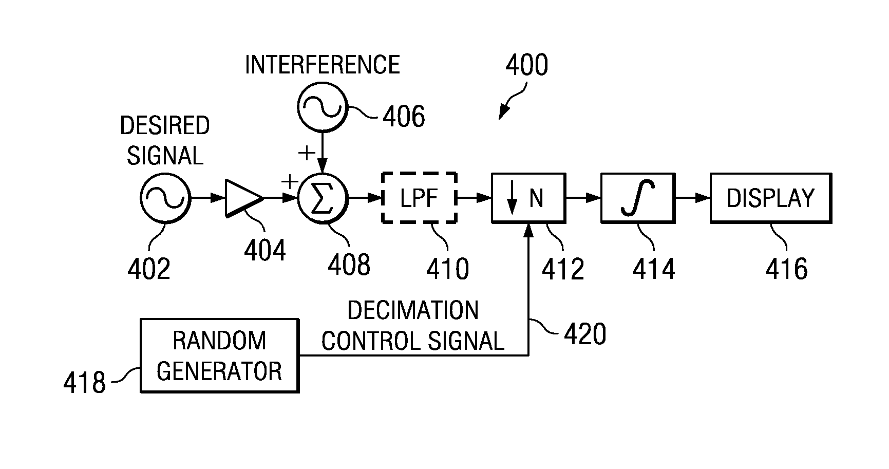
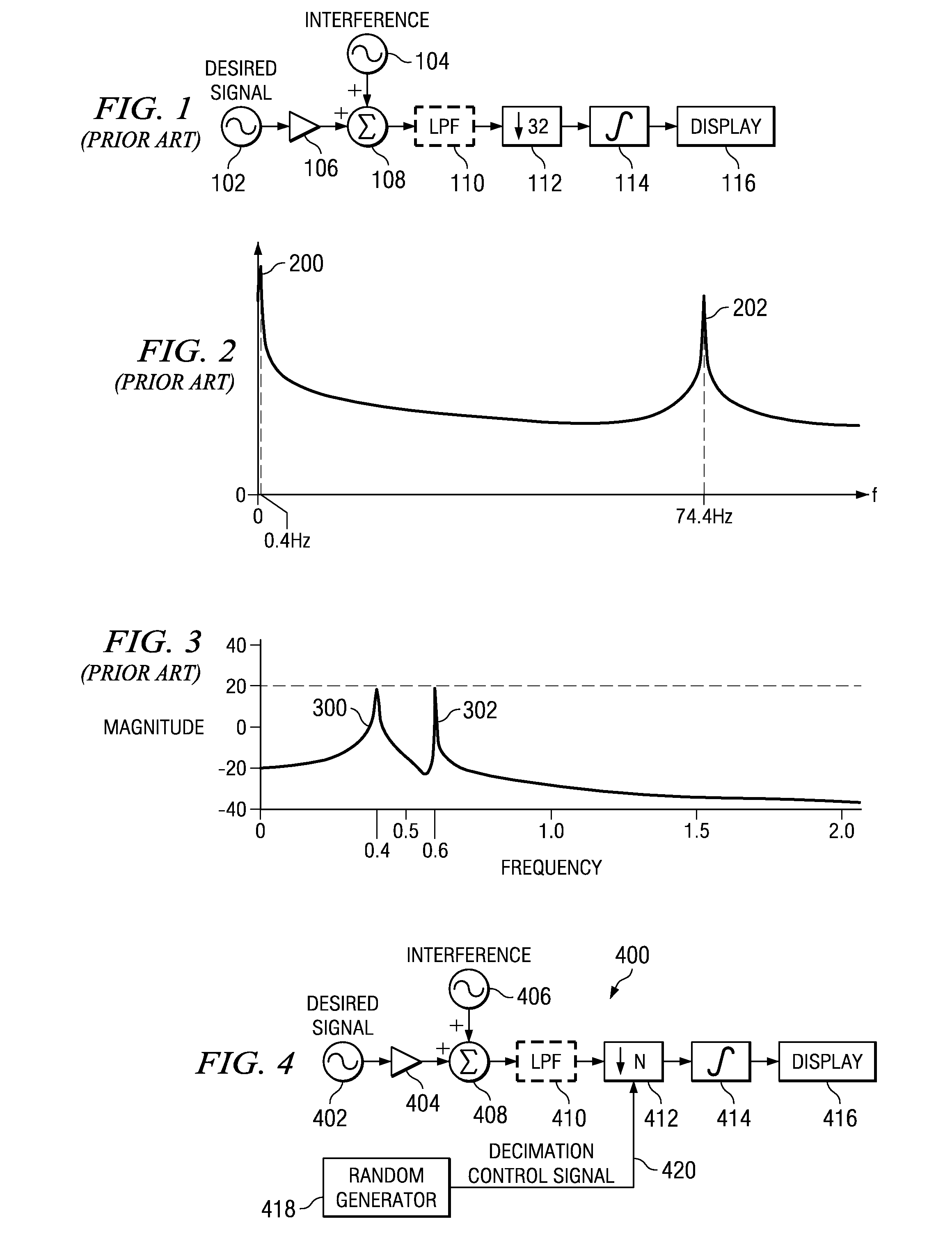
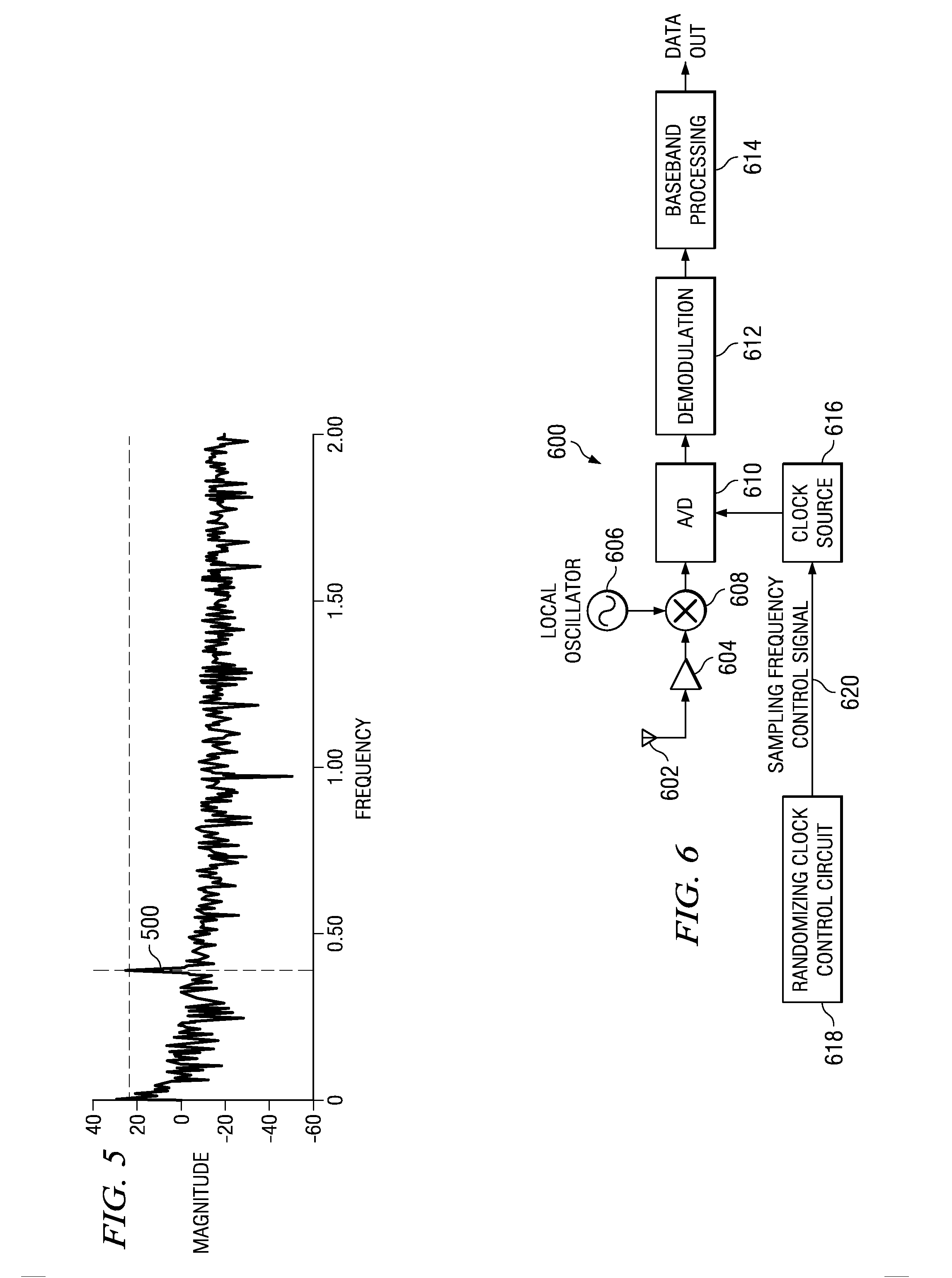
The present invention provides a method and apparatus for suppressing aliasing interferers in discrete time decimating and sub-sampling systems. The invention is applicable to various types of systems and can be used to eliminate the need for expensive anti-aliasing filters. The invention involves modifying the sub-sampling rate or decimation ratio in a random manner to cause the interfering signals to fold in at a different frequency at each cycle, resulting in reduced noise levels. The sampling frequency is dynamically changed to prevent interfering signals from buildup at any one frequency. The invention effectively suppresses aliasing interferers by spreading the energy of the interfering signals out over a wider spectrum. The range of sampling frequencies can be controlled to prevent interfering energy buildup at any one frequency. The invention can be implemented as software objects or hardware circuits.

Problems solved by technology

If it is desired to sample at a lower rate, the lower the sampling rate the more unwanted signals fold in and interfere with the desired signal.
The level of the resulting noise floor is not nearly as strong as the original interfering signal.
The larger the range of sampling frequencies, the larger the interference spreading factor resulting in lower noise levels.

Method used


Image

  • System for suppressing aliasing interferers in decimating and sub-sampling systems
  • System for suppressing aliasing interferers in decimating and sub-sampling systems
  • System for suppressing aliasing interferers in decimating and sub-sampling systems

Examples


Embodiment Construction

Notation Used Throughout

[0029] The following notation is used throughout this document.

TermDefinitionA / DAnalog to DigitalASICApplication Specific Integrated CircuitC / NCarrier to NoiseDSPDigital Signal ProcessorFPGAField Programmable Gate ArrayHDLHardware Description LanguageISMIndustrial Scientific MedicalLOLocal OscillatorLPFLow Pass FilterTDDTime Division Duplex

Detailed Description of the Invention

[0030] The present invention is a method and apparatus for suppressing aliasing interferers in decimating and sub-sampling systems. The invention is applicable for use in numerous types of systems and is particular applicable to sub-sampling and sample rate decimating discrete time systems. For example, the invention is applicable in TDM applications such as Bluetooth environments. The invention can be used to eliminate altogether the need for a costly anti-aliasing filter having demanding requirements. Alternatively, the present invention can be used to significantly reduce the requ...


PUM


Abstract

A novel and useful method and apparatus for suppressing aliasing interferers in decimating and sub-sampling discrete time systems. The present invention is operative to reduce the requirements for or completely eliminate the need for the anti-aliasing filter by dynamically modifying the sub-sampling rate (or decimation ratio). Rather than maintain a constant sampling rate (or decimation ratio), the sampling rate (or decimation ratio) is randomized such that its average remains at the nominal value and the effective jitter is low enough for the low rate (or low decimation ratio) system to tolerate. This smears or spreads interfering signals across the spectrum resulting in a noise floor at a significantly reduced level much lower than that of the original interferer signal. The interfering signals are reduced to background noise wherein the level of the resulting noise floor is not nearly as strong as the original interfering signal. Aliasing interferers are effectively suppressed by spreading the energy of the interfering signals out over a wider spectrum.

Description

FIELD OF THE INVENTION [0001] The present invention relates to the field of data communications and more particularly relates to an apparatus and method for suppressing aliasing interferers in decimating and sub-sampling systems. BACKGROUND OF THE INVENTION [0002] In sub-sampling and sample rate decimating discrete time systems it is necessary to suppress interferers whose frequencies fall within the aliasing bandwidths of the particular system. For this reason, anti-aliasing filters are used to suppress these interferers. The requirements of these anti-aliasing filters, however, are typically very demanding due to the level of interference encountered, bandwidths of the desired and interfering signals, desired suppression, etc. The demanding requirements of the anti-aliasing filter typically results in having to design in costly analog filters or high gate count digital filters. In some cases, it is too cost prohibitive to include an anti-aliasing filter in the system and performan...

Claims


Application Information

Patent Timeline
Patent Type & Authority Applications(United States)
IPC IPC(8): H03M7/00
CPCH03H17/0219H03H17/0416H03H17/0621
Inventor KATZ, RAN
Owner TEXAS INSTR INC
Learn More