Integrated light sensitive liquid crystal display

a liquid crystal display and light-sensitive technology, applied in the field of touch-sensitive displays, can solve the problems of increasing the complexity of display, and increasing the cost of display

Inactive Publication Date: 2007-05-17
APPLE INC
View PDF105 Cites 261 Cited by
  • Summary
  • Abstract
  • Description
  • Claims
  • Application Information

AI Technical Summary

Problems solved by technology

The optically-based touch screen increases the expense of the display, and increases the complexity of the display.
The inclusion of the photosensors and associated computer increases the expense of the display, and increases the complexity of the display.
Similar to touch sensitive structures affixed to the front of the liquid crystal stack, the light sensitive material affixed to the rear of the liquid crystal stack similarly pose potential problems limiting contrast of the display, increasing the expense of the display, and increasing the complexity of the display.
For example, the transparent surface, and other layers between the liquid crystal material and the transparent surface may result in multiple reflections which decreases the display's contrast and produces glare.
Moreover, adding an additional touch panel to the display increases the manufacturing expense of the display and increases the complexity of the display.
Also, the incorporation of the touch screen reduces the overall manufacturing yield of the display.

Method used


Image

  • Integrated light sensitive liquid crystal display
  • Integrated light sensitive liquid crystal display
  • Integrated light sensitive liquid crystal display

Examples


Embodiment Construction

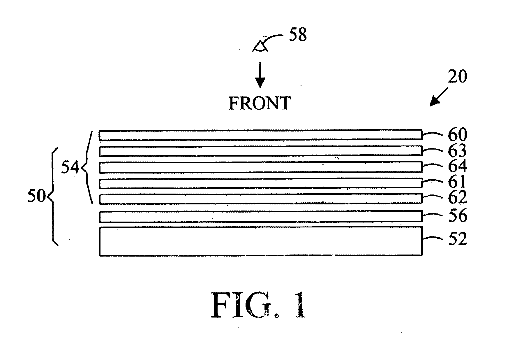
[0050] Referring to FIG. 1, a liquid crystal display (LCD) 50 (indicated by a bracket) comprises generally, a backlight 52 and a light valve 54 (indicated by a bracket). Since liquid crystals do not emit light, most LCD panels are backlit with fluorescent tubes, xenon flat lamp, or arrays of light-emitting diodes (LEDs) that are built into the sides or back of the panel. To disperse the light and obtain a more uniform intensity over the surface of the display, light from the backlight 52 typically passes through a diffuser 56 before impinging on the light valve 54.

[0051] The transmittance of light from the backlight 52 to the eye of a viewer 58, observing an image displayed on the front of the panel, is controlled by the light valve 54. The light valve 54 normally includes a pair of polarizers 60 and 62 separated by a layer of liquid crystals 64 contained in a cell gap between glass or plastic plates, and the polarizers. Light from the backlight 52 impinging on the first polarizer ...


PUM


Abstract

A liquid crystal device including a front electrode layer, rear electrode layer, a liquid crystal material located between the front electrode layer and the rear electrode layer. A polarizer is located between the liquid crystal material and the front electrode layer and changing an electrical potential between the rear electrode layer and the front electrode layer modifies portions of the liquid crystal material to change the polarization of the light incident thereon. A plurality of light sensitive elements are located together with the rear electrode layer and a processor determines the position of at least one of the plurality of light sensitive elements that has been inhibited from sensing ambient light.

Description

CROSS-REFERENCE TO RELATED APPLICATIONS [0001] This application claims the benefit of U.S. Provisional App. No. 60 / 736,708, filed Nov. 14, 2005.BACKGROUND OF THE INVENTION [0002] The present invention relates to touch sensitive displays. [0003] Touch sensitive screens (“touch screens”) are devices that typically mount over a display such as a cathode ray tube. With a touch screen, a user can select from options displayed on the display's viewing surface by touching the surface adjacent to the desired option, or, in some designs, touching the option directly. Common techniques employed in these devices for detecting the location of a touch include mechanical buttons, crossed beams of infrared light, acoustic surface waves, capacitance sensing, and resistive sensing techniques. [0004] For example, Kasday, U.S. Pat. No. 4,484,179 discloses an optically-based touch screen comprising a flexible clear membrane supported above a glass screen whose edges are fitted with photodiodes. When th...

Claims


Application Information

Patent Timeline
Patent Type & Authority Applications(United States)
IPC IPC(8): G09G3/36G06F3/041
CPCG02F1/13318G02F1/13338G02F1/133512G02F2001/13312G02F2001/133616G06F3/0412G06F3/042G06F2203/04109G06F3/0416G02F1/13312G02F1/133616
Inventor DEN BOER, WILLEMABILEAH, ADIEL
Owner APPLE INC
Why Eureka
Try Eureka