Portable electronic apparatus

a technology of electronic equipment and portable structure, which is applied in the direction of electrical equipment construction details, instruments, television systems, etc., can solve the problems of deteriorating heat radiation efficiency, inability to securely transfer the heat of the drive substrate, and inability to securely transfer the heat of the heat radiating plate, etc., to achieve thin structure and improve heat radiating efficiency

Active Publication Date: 2007-05-17
MAXELL HLDG LTD
View PDF7 Cites 14 Cited by
  • Summary
  • Abstract
  • Description
  • Claims
  • Application Information

AI Technical Summary

Benefits of technology

[0014] Accordingly, it is possible to provide a portable electronic apparatus which improves a heat radiating efficiency and intends to achieve a further thin structure.

Problems solved by technology

In the case that the interval of the gap is large, the contact pressure becomes low, so that there is a problem that it is impossible to securely transfer the heat of the drive substrate 2 to the heat radiating plate and an efficiency of the heat radiation is deteriorated.
Accordingly, it is necessary to secure a space for the connector in the outer shell part side, and there is a problem that a thin structure is obstructed.

Method used


Image

  • Portable electronic apparatus
  • Portable electronic apparatus
  • Portable electronic apparatus

Examples


Embodiment Construction

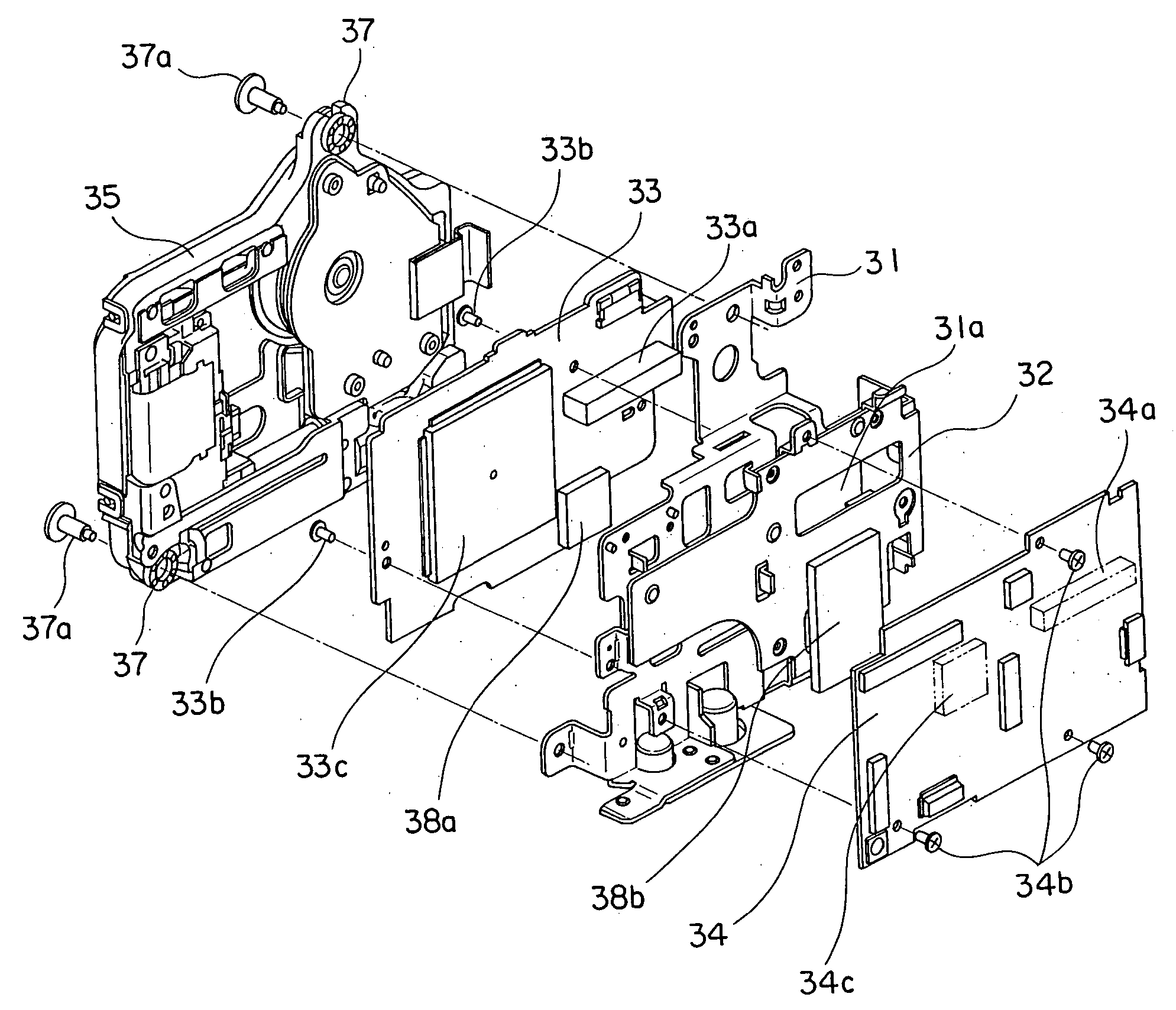
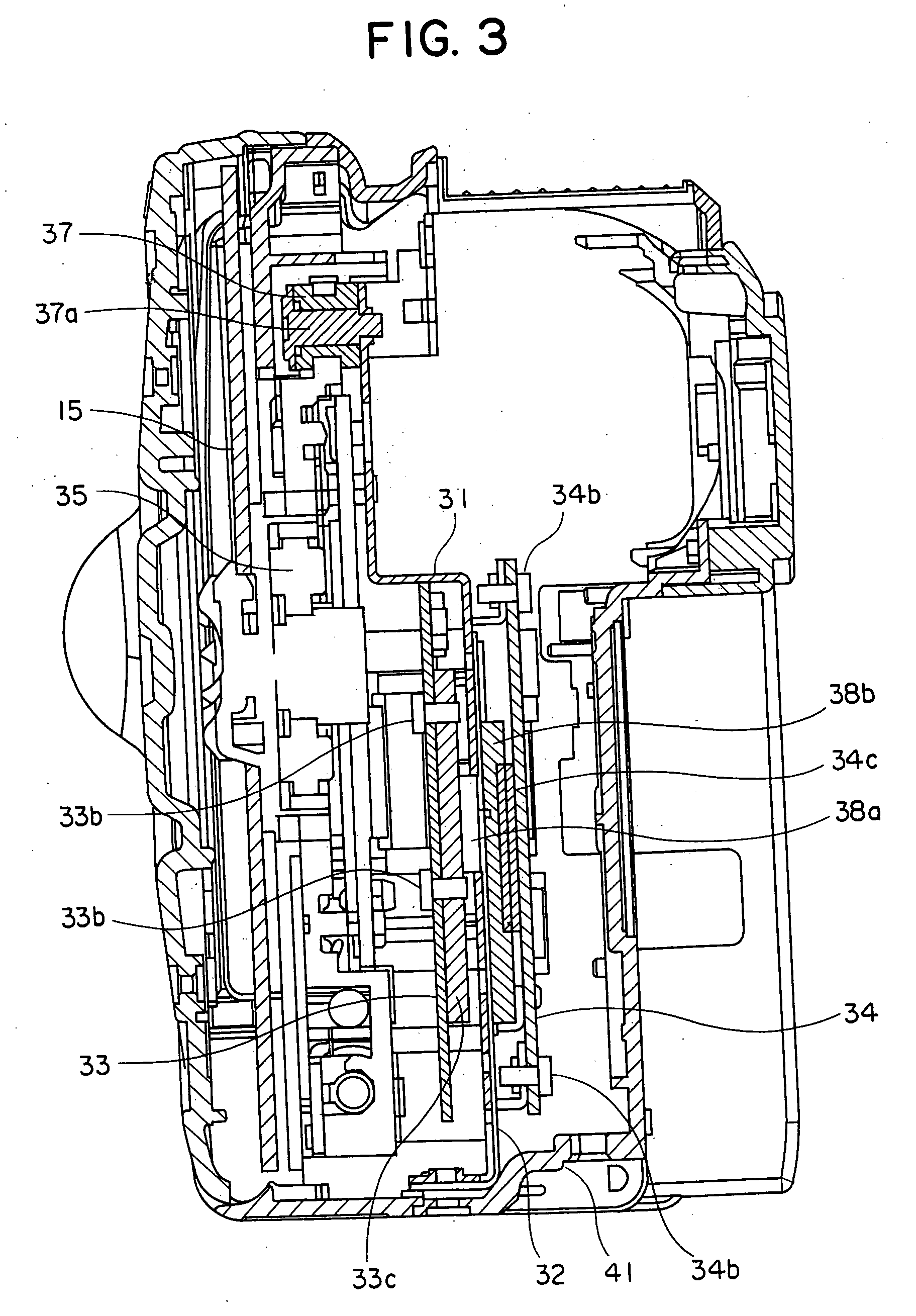
[0026] A description will be given below of an example of a video camera as a first embodiment in accordance with the present invention with reference to FIGS. 1 to 7.

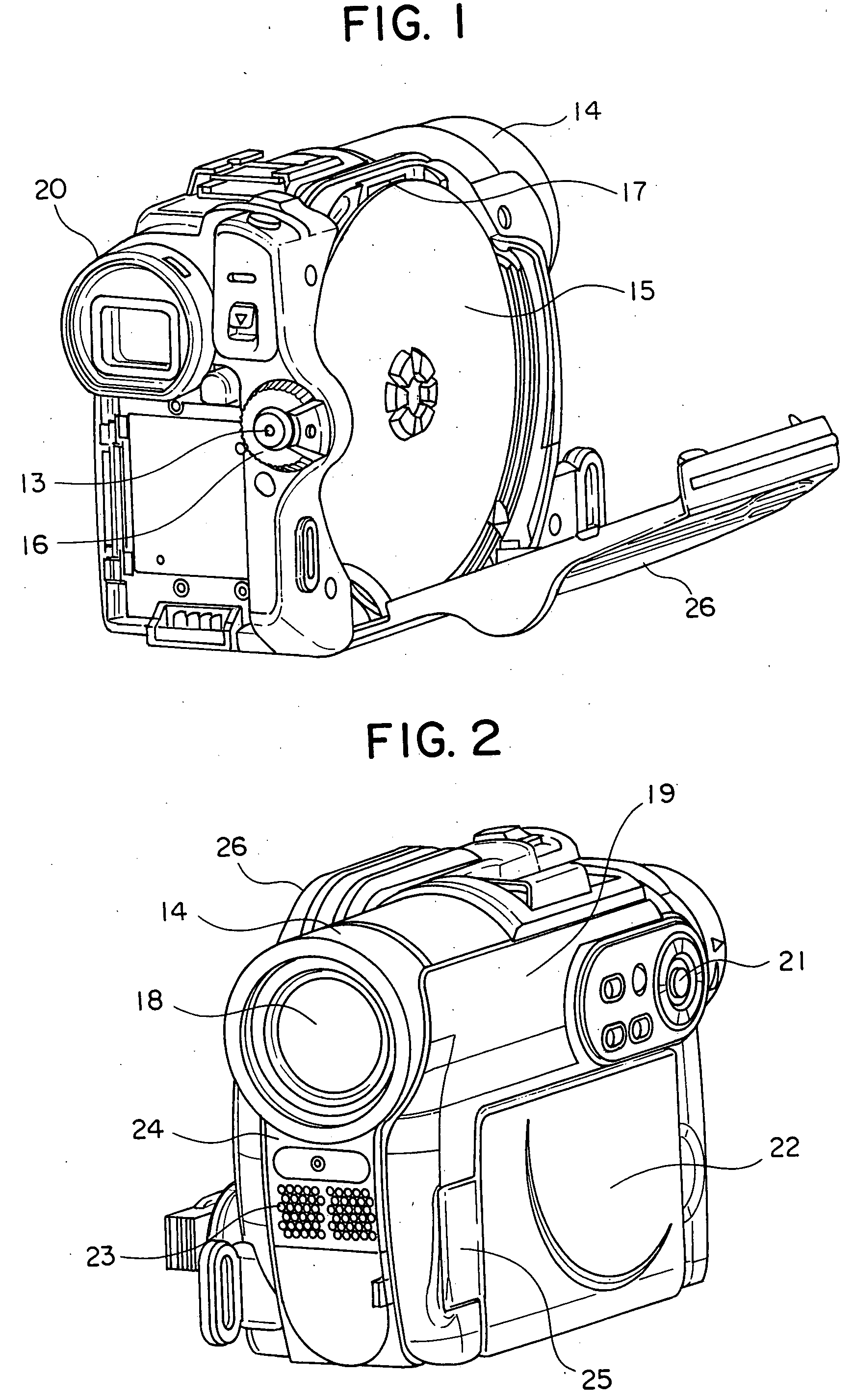
[0027] A description will be first given of a summary of the video camera using an optical disc in accordance with the present embodiment with reference to FIGS. 1 and 2. FIG. 1 is a rearward perspective view of a state in which a disc cover of the video camera in accordance with the present embodiment is open, and FIG. 2 is a frontward perspective view of the video camera in accordance with the present embodiment.

[0028] The video camera in accordance with the present embodiment is sectioned into a front side constituted by a lens portion 18, a microphone portion 23, a lens cover 14, a front case 24 and the like, a liquid crystal display side constituted by a liquid crystal display (LCD) panel portion 22, an LCD supporting point portion 25, a main body case 19 and the like, a grip side constituted by a disc cover 26,...


PUM


Abstract

In a portable electronic device having two circuit boards having a heat generating electronic device, a frame arranged at a position pinched between the circuit boards, a first heat radiating plate brought into contact with the frame and having a higher thermal conductivity than the frame, and a second heat radiating member transferring a heat between the first heat radiating member and two circuit boards, each of two circuit boards is fixed to the frame and two circuit boards are directly connected by a connector. Accordingly, it is possible to provide the portable electronic device which can improve a heat radiating efficiency and achieve a further thin structure.

Description

INCORPORATION BY REFERENCE [0001] The present application claims priority from Japanese application JP2005-328247 filed on Nov. 14, 2005, the content of which is hereby incorporated by reference into this application. BACKGROUND OF THE INVENTION [0002] The present invention relates to a technique of a portable electronic apparatus loading an electronic device thereon. [0003] As a background art of the present technical field, for example, there is JP-A-2004-253752 (patent document 1). In the present publication, there is described “an object is to intend to make an electronic apparatus compact” as a problem. Further, there is described “an electronic apparatus having an electronic device generating heat and an electronic device in which a used environmental temperature is lower than a temperature generated from the electronic device, comprising a support means supporting a casing of the electronic apparatus, and a heat conducting means arranged between the support means and the heat...

Claims


Application Information

Patent Timeline
Patent Type & Authority Applications(United States)
IPC IPC(8): H05K7/20G03B17/02
CPCH04N5/2251G03B17/55
Inventor SENGOKU, EISUKETADOKORO, KEIICHI
Owner MAXELL HLDG LTD
Why Eureka
Try Eureka