
Optical pickup device

a pickup device and optical technology, applied in the direction of data recording, instruments, disposition/mounting of heads, etc., can solve the problems of not being able to detect a designated error signal, a lot of trouble and time with the production of optical pickup devices, and an obstacle in miniaturizing the photo pickup devi

Inactive Publication Date: 2007-05-17
JVC KENWOOD CORP A CORP OF JAPAN
View PDF5 Cites 9 Cited by
  • Summary
  • Abstract
  • Description
  • Claims
  • Application Information

AI Technical Summary

Benefits of technology

[0026] Under a situation mentioned above, an object of the present invention is to provide an optical pickup device capable of providing the advantages of the astigmatism method and the advantages of the spot-size method using a hologram element, simultaneously.

Problems solved by technology

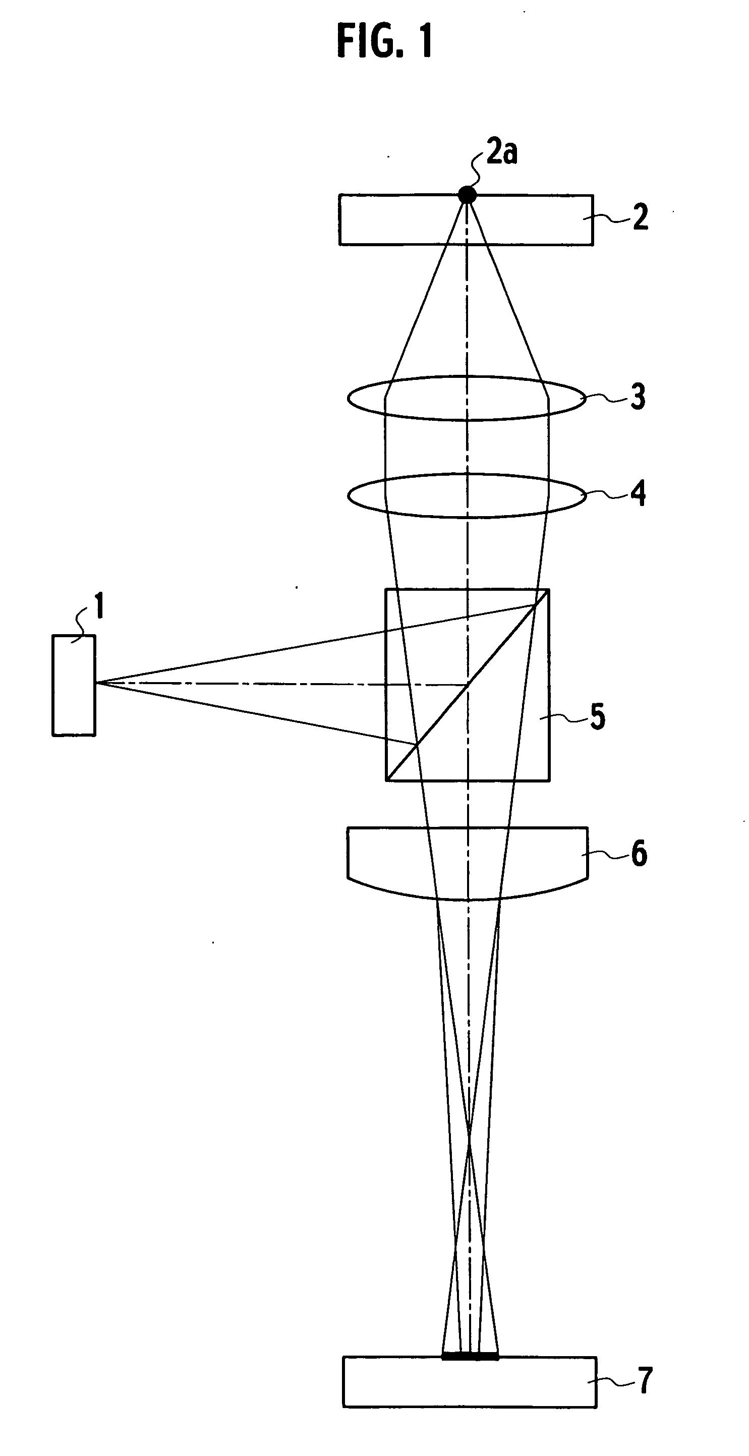
Further, since the respective components (i.e. the light source 1, the beam splitter 5, the collimator lens 4, the objective lens 3, the cylinder lens 6 and the photo detective element 7) have to be disposed apart from each other by predetermined distances, the arrangement might be an obstacle in miniaturizing the photo pickup device.
As it is unavoidable that the performances of the cylinder lens 6, the beam splitter 5 and the collimator lens 4 and the assembling positions of constituents of the light source 1 (including a semiconductor laser) fluctuate, it is required to adjust the assembling positions of the cylinder lens 6 and the photo detective element 7, taking a lot of trouble and time with the production of an optical pickup device.
Further, depending on variations per hour in the assembling positions of the constituents, it becomes impossible to detect a designated error signal.
It means that it is impossible to convert electric signal processing circuits widely used in the astigmatism method to a circuits for the photo pickup device.
Thus, although the conventional photo pickup device adopting a hologram element is easy to be small-sized in comparison with the conventional photo pickup device shown in FIG. 1, there is a limit to the miniaturization due to the large-sized photo detective element 9 and an increase in the number of output terminals.
Further, since the calculation of output signals is complicated, drastic changes would be required for widely-used electric signal processing circuits dealing with the astigmatism method.

Method used


Image

  • Optical pickup device
  • Optical pickup device
  • Optical pickup device

Examples


first embodiment

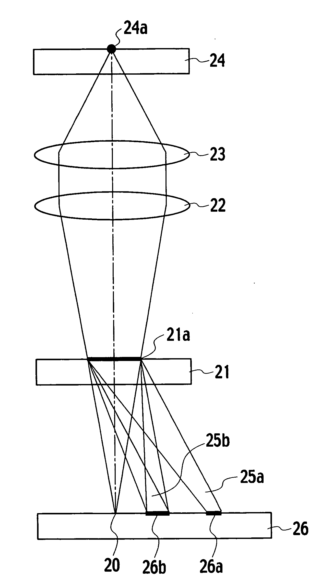
[0074]FIG. 9 is a structural view of an optical pickup device in accordance with the present invention. In the figure, light radiated from a semiconductor laser 20 as a light source is transmitted through a hologram element 21, a collimator lens 22 and an objective lens 23, in order. Then, the light is converged by the objective lens 23 to form a light spot 24a on an optical disc 24. The optical disc 24 is formed by, for example, CD (Compact Disc), DVD (Digital Versatile Disc) or the like.

[0075] The light spot 24a is reflected by the optical disc 24 and successively transmitted to the hologram element 21 through the objective lens 23 and the collimator lens 22, in order. The reflection light reflected from the optical disc 24 and entering an area 21a of the hologram element 21 is emitted in diffraction, in the form of two diffraction lights 25a, 25b. These diffraction lights 25a, 25b enter a photo detective element 26 and form two light spots 26a, 26b on the same element 26.

[0076] ...

embodiment

3rd. Embodiment

[0095] According to the third embodiment of the invention, four divided areas 30a˜30d of the hologram element 21 are characterized by diffracting the light reflected on the photo disc and further impressing astigmatism on the diffraction lights, similarly to the second embodiment of the invention. Different from the second embodiment, however, the photo detective element 26 is composed of ten divided detective parts 261A˜261J, as shown in FIGS. 19˜21.

[0096] In detail, as shown in FIGS. 19˜21, the photo detective element 26 comprises three divided detective parts 261A, 261B and 261C receiving the diffraction light from the divided area 30b of the hologram element 21 shown in FIG. 10, three divided detective parts 261D, 261E and 261F receiving the diffraction light from the divided area 30d, two divided detective parts 261G and 261H receiving the diffraction light from the divided area 30a and two divided detective parts 261I and 261J receiving the diffraction light fr...

fourth embodiment

[0105] In order to allow the divided detective part for receiving the light spot 45b to output signals corresponding to the areas A2 and B1 separately, the divided detective part 261B for receiving the light spot 45b is divided into two parts 261B-1 and 261B-2 and additionally, the divided detective part 261E for receiving the light spot 45d is also divided into two parts 261E-1 and 261E-2, as shown in FIG. 22, allowing the tracking error signal to be detected by the phase-difference method. Note that if the relative distance between the objective lens 23 and the optical disc 24 changes from that in the in-focus position, the divided detective parts 261B-1 and 261B-2 receive the light spot 46b of FIG. 23 and the light spot 47b of FIG. 24, while the divided detective parts 261E-1 and 261E-2 receive the light spot 46d of FIG. 23 and the light spot 47d of FIG. 24.

[0106] Assume that in this embodiment respective output signals from the divided detective parts 261B-1, 261B-2, 261E-1 and...


PUM

PropertyMeasurementUnit
optical poweraaaaaaaaaa
diameteraaaaaaaaaa
relative distanceaaaaaaaaaa

Abstract

In a photo pickup device, an incident area 30 for a reflection light of a light spot is divided into four areas 30a˜30d by parting lines 31, 32 making axial-symmetrical angles with a direction Y of a projected track on an optical disc. In these areas, the so-divided areas 30a, 30c are formed so as to diffract the light in one or more directions in a range of 90 degrees ±20 degrees to the direction Y and impress misalignment on each diffraction light. In each diffraction light, two focal lines produced due to the astigmatism make approx. 45 degrees with the direction Y of the projected track. Further, the divided areas 30b, 30d are characterized by diffracting the light in one or more directions in a range of 90 degrees ±20 degrees to the direction Y.

Description

BACKGROUND OF THE INVENTION [0001] 1. Field of the Invention [0002] The present invention relates to optical pickup devices, and more particularly, an optical pickup device which includes a hologram element as a detection optical element and which carries out recording / playing of information in relation to an optical disc optically. [0003] 2. Description of the Related Art [0004] In such an optical pickup device that carries out recording / playing of information in relation to an optical disc optically, there have been adopted an astigmatism method for detecting a focus-servo error signal and a push-pull method for detecting a tracking-servo error signal. [0005]FIG. 1 is a structural view showing one example of a conventional optical pickup device. In the figure, light radiated from a light source 1 is reflected by a beam splitter 5, transmitted through a collimator lens 4 and converged by an objective lens 3 to form a light spot 2a in an optical disc 2. Then, the light (the light sp...

Claims


Application Information

Patent Timeline
Patent Type & Authority Applications(United States)
IPC IPC(8): G11B7/00
CPCG11B7/0903G11B7/0909G11B7/0912G11B7/131G11B7/1353G11B7/09
Inventor HIRAGA, TAKAYOSHIKANEKO, TAKAHIROOHYAMA, MINORU
Owner JVC KENWOOD CORP A CORP OF JAPAN
Learn More