Eureka AIR delivers breakthrough ideas for toughest innovation challenges, trusted by R&D personnel around the world.

Processing apparatus

a processing apparatus and processing technology, applied in the field of processing apparatuses, can solve the problem that it is difficult to reduce the influence degree of particles on wafers sufficiently, and achieve the effect of preventing object pollution

Inactive Publication Date: 2007-05-17
TOKYO ELECTRON LTD
View PDF16 Cites 15 Cited by
  • Summary
  • Abstract
  • Description
  • Claims
  • Application Information

AI Technical Summary

Benefits of technology

[0015] This invention has been made based on the above consideration, and an object of the invention is to provide a processing apparatus for processing an object to be processed contained in a hermitic container, wherein it is possible to reduce as far as possible an adverse effect of a particle in an outside space area against the object to be processed and against an inside space area and to surely prevent pollution of the object to be processed, when the outside space area in which the carrier is transferred and placed and the inside space area which is kept in clean atmosphere, for example, are communicated with each other.
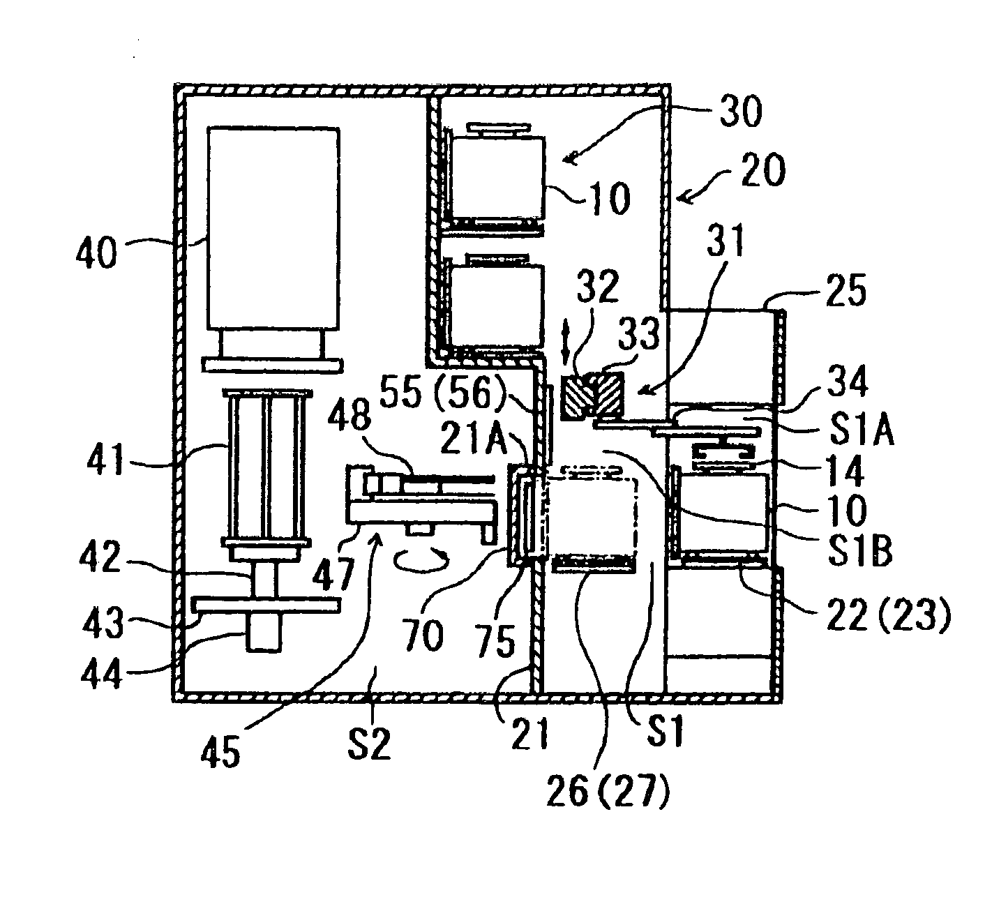
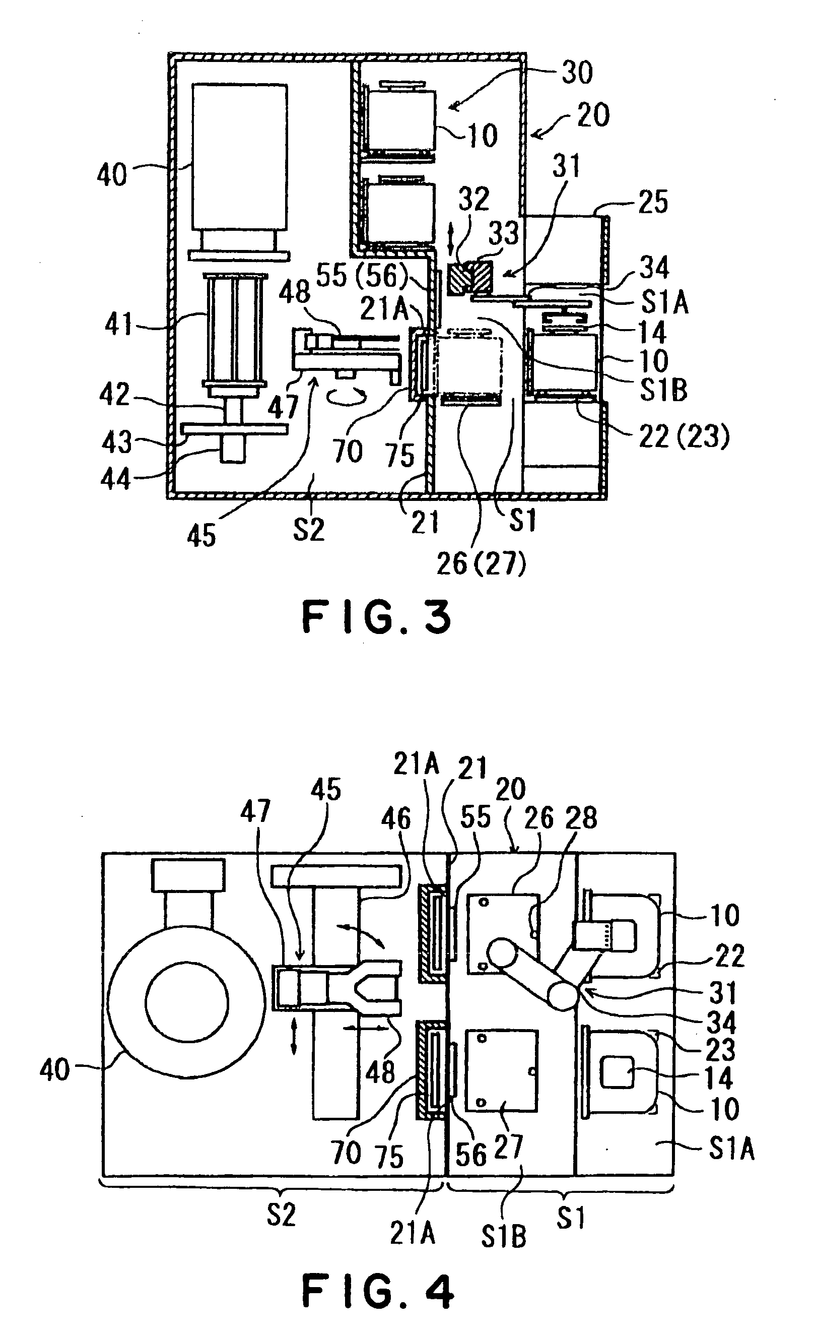
[0017] According to the present invention, the driving unit that moves the lid opening-and-closing mechanism away from the container is located inside a driving-unit arrangement room formed separately from a door-mechanism space which is formed between the door mechanism itself and the container by the door mechanism, and the gas-discharging mechanism is provided to discharge the gas in the drive-unit arrangement room, so that a dust is removed by the gas-discharging mechanism even when the dust is generated by movement of the driving unit for opening and closing the lid of the container. Therefore, it is surely prevented that the dust enters into the door-mechanism space and adheres on the object to be processed in the container, and also prevented that the clean atmosphere and so on in the inside space area is polluted when the door mechanism is opened. As a result, a degree of the adverse effect by the dust (particle) against the object to be processed is restrained to be small and the object to be processed to which a predetermined process has been conducted can keep a high clean level.
[0019] In this case, possibility that a dust is generated by a withdrawing movement of the door mechanism is reduced. Therefore, it is more surely prevented that the object to be processed or the clean atmosphere in the inside space area are polluted by the dust.
[0021] In this case, it is possible to prevent that the door-mechanism space is exposed to the atmosphere in the outside space area even when the container is not located at a predetermined position (on the stage, for example). Therefore, it is surely prevented that a dust floating in the outside space area, for example, enters into the door-mechanism space.
[0023] Incidentally, if the space inside the carrier and the space of the inside space area are communicated with each other at once, a dust existing in the door-mechanism space rises up due to a pressure difference between a pressure inside the carrier and a pressure in the inside space area, and then adheres on the object to be processed in the container and mixes into the inside of inside space area. Therefore, it is preferable that the door mechanism has a pressure-adjusting mechanism that can gradually open through one space and the other space with respect to the door mechanism in order to leisurely reduce a difference pressure between the both spaces to substantially zero.

Problems solved by technology

However, even though the techniques as described above are used, it is actually still difficult to sufficiently reduce an influence degree of particles upon wafers, when a space in an outside space area, in which a carrier containing the wafers is placed, and a space in an inside space area, in which a predetermined process is conducted to the wafers, are communicated with each other.

Method used


Image

  • Processing apparatus
  • Processing apparatus
  • Processing apparatus

Examples


Embodiment Construction

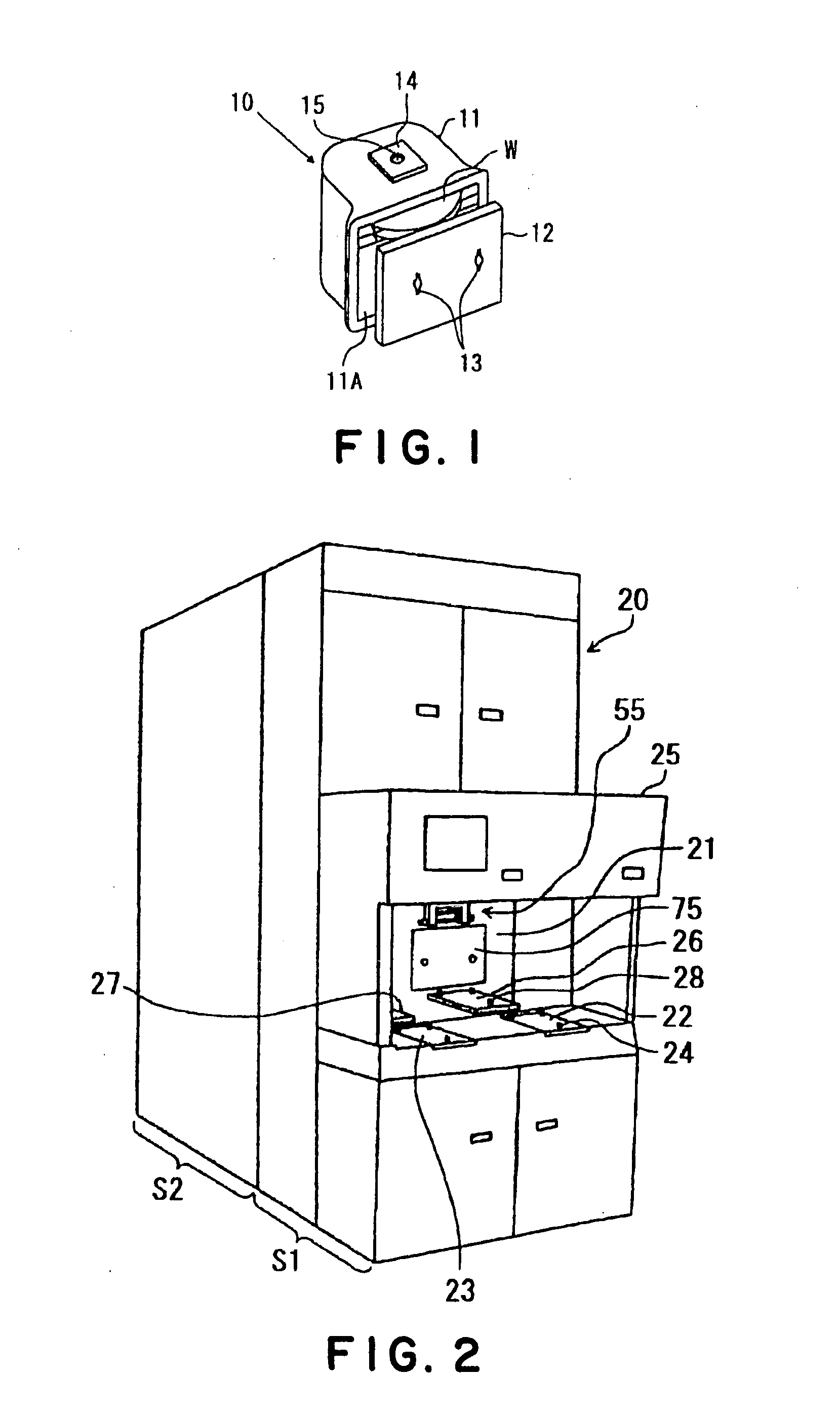
[0034] In a processing apparatus of the present invention, a hermetic container containing an object to be processed is placed at a predetermined position, and then the object to be processed is taken out from the container, and conveyed into an inside space area, which is maintained under a clean atmosphere, to be subjected to a predetermined process.

[0035] A carrier 10 including a main carrier body 11 is used, for example, as a container containing the object to be processed, as shown in FIG. 1. A taking-out port 11A is opened at one surface of the main carrier body 11. The taking-out port 11A is closed by a lid 12 that is provided to be removable. The carrier 10 is, for example, made of resin. The object to be processed is, for example, a wafer W whose diameter is 300 mm. The carrier 10 is composed so as to be capable of holding a plurality of, for example, 25 wafers W in a tier-like manner.

[0036] The lid 12 of the carrier 10 includes a not-shown latch mechanism (a lock mechani...


PUM


Abstract

The present invention is a processing apparatus for an object to be processed, the processing apparatus including: a partition that defines an outside space area in which a container hermetically containing an object to be processed and having a lid is conveyed, and an inside space area in which the object to be processed taken out from the container is conveyed; an opening part provided in the partition, through which the two space areas are communicated with each other; a door mechanism that can close the opening part; a lid opening-and-closing mechanism provided at the door mechanism, and capable of opening and closing the lid of the container located at a predetermined position in the outside space area under a situation wherein the door mechanism closes the opening part; a driving unit that moves the lid opening-and-closing mechanism away from the container relatively to the door mechanism; a cover member that defines a driving-unit arrangement room, in which the driving unit is contained, in the door mechanism; and a gas-discharging mechanism that discharges a gas in the driving-unit arrangement room.

Description

TECHNICAL FIELD [0001] The present invention relates to a processing apparatus that takes out an object to be processed from a hermetic container and conducts a predetermined process to the object to be processed. BACKGROUND ART [0002] As one of semiconductor manufacturing apparatuses, for example, there is a thermal processing apparatus that conducts a heat treatment to a plurality of semiconductor wafers (hereafter, to be simply referred to as “wafer”) in a batch. This thermal processing apparatus is provided with a conveying in-and-out area where a carrier that is a container containing a plurality of wafers is conveyed in and out by an automatic conveying robot or by an operator, and a loading area where the wafers in the container are transferred and placed onto a wafer boat that is a substrate holder and are conveyed in and out from a heat treating furnace. [0003] In this thermal processing apparatus, an atmosphere in the loading area is kept cleaner than an atmosphere in the ...

Claims


Application Information

Patent Timeline
IPC IPC(8): B65B69/00B65G49/07H01L21/677B65G49/00
CPCH01L21/67772H01L21/68
Inventor OYAMA, KATSUHIKOMOCHIDUKI, SHINYATAKEUCHI, YASUSHI
Owner TOKYO ELECTRON LTD
Why Eureka
Eureka Blog
Learn More