Dental implant

Inactive Publication Date: 2007-05-17
GC CORP
View PDF18 Cites 20 Cited by
  • Summary
  • Abstract
  • Description
  • Claims
  • Application Information

AI Technical Summary

Benefits of technology

[0012] Further, the followings were also found out. In the dental implant, an intra-oral side end portion of the collar portion is formed in a curved surface shape, and the curved surface is subjected to the surface roughening treatment. Then, since the bone covers the portion in the curved surface shape, retaining force of the dental implant in the bone can be increased. Further, the intra-oral side top end surface of the collar portion is perpendicular to the longitudinal axis, and the intra-oral side top end surface is not subjected to the surface roughening treatment. Then, the bone is hardly grown up to the intra-oral side top end surface, and a comparatively stable periodontal tissue can be easily formed with a tooth, gingiva and a dental implant. Furthermore, when the bellied portion of the collar portion is formed in the columnar shape, the growth of bone is not badly influenced since a part having an acute angle is decreased if the collar portion has the same height. So, it is preferable. Further, it is preferable that surfaces subjected to the surface roughening treatment have ten point average roughness (Rz) of 2 to 60 μm, or grooves or threads with 0.05 to 0.5 mm depth and width.
[0013] Further, the following were also found out. The crest diameters of the complete thread portion of the external thread portion may be equal along the longitudinal axis, or may be reduced or have a reduced diameter part as apart from the intra-oral side. When the external thread portion comprises a multiple-start thread, a pitch of the external thread portion is increased as a result, so that the dental implant can be embedded rapidly in an embedding hole formed in the jawbone. Thus, a patient's burden can be reduced and the dental treatment efficiency of an operator can be increased. Further, an end portion on the opposite side to the intra-oral side comprises a projected hemispherical shaped portion which begins from the root diameter of the complete thread portion of the external thread portion at the end portion on the opposite side to the intra-oral side. Then, it is preferable that the hemispherical shaped portion hardly presses a conical shaped portion formed at a top end portion of the embedding hole and damages the tooth, when the dental implant is embedded in the embedding hole formed in the jawbone of the lost tooth portion. Further, the intra-oral side of the internal thread portion has a recessed portion in a truncated conical shape having diameters which expand up toward the intra-oral side. Then, the abutment fixed on the intra-oral side of the dental implant can be fit certainly and strongly. Furthermore, the intra-oral side of the internal thread portion has a rotation prevention part between the recessed portion in the truncated conical shape and the internal thread portion. Then, the abutment, which is fixed on the intra-oral side of the dental implant, can be certainly positioned and fixed in non-rotational state.
[0014] Such a dental implant according to the present invention is same as the conventional dental implant in two points that is that it has the internal thread portion screwed along the longitudinal axis, and that it has the external thread portion screwed on the side periphery thereof, in which the external thread portion at least has the largest crest diameter of the complete thread por

Problems solved by technology

One cause is that local stress concentration is generated around the borderline between the dental implant and the abutment.
However, when the cutout

Method used


Image

  • Dental implant
  • Dental implant
  • Dental implant

Examples


Embodiment Construction

[0020] Hereinafter, the dental implant according to the present invention is described concretely with drawings.

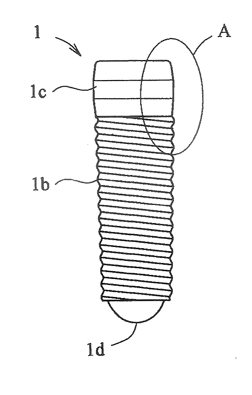
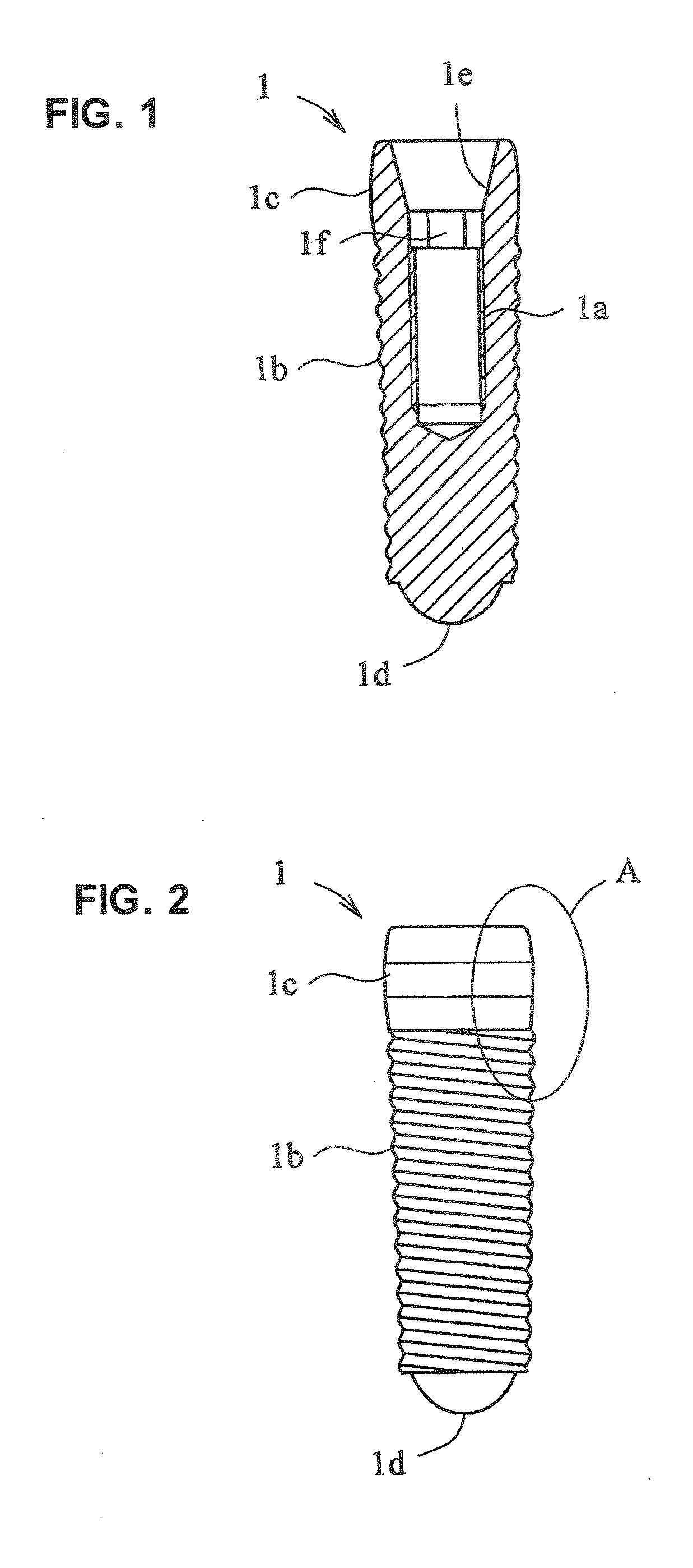
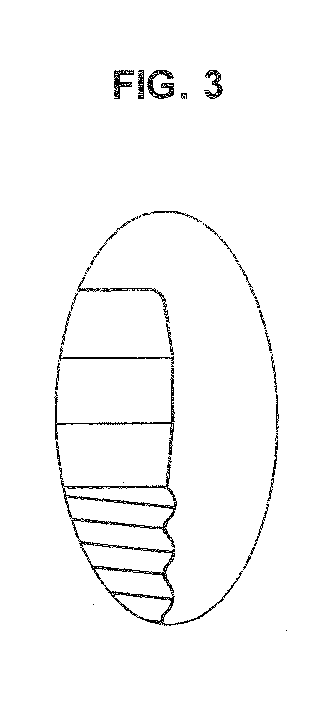
[0021]FIG. 1 is a longitudinal sectional explanation view illustrating one example of a dental implant according to the present invention. FIG. 2 is a front view ofFIG. 1. FIG. 3 is an enlarged explanation view of the A portion of FIG. 2.

[0022] In the drawings, reference numeral 1 is a dental implant according to the present invention, which is generally made of titanium or titanium alloy. The dental implant 1 comprises an internal thread portion 1a screwed along a longitudinal axis, an external thread portion 1b screwed on a side periphery, in which at least a crest diameter of a complete thread portion at the most intra-oral side is a largest crest diameter, and a collar portion 1c provided on the intra-oral side of the external thread portion 1b and formed to have diameters that expand up from a portion including a root diameter portion of the complete thread portion ...


PUM


Abstract

To restrict bone absorption occurring as time elapses after osseous integration, a dental implant comprises an internal thread 1a; an external thread 1b having a largest crest diameter of a complete thread at the most intra-oral side; and a collar portion 1c provided on the intra-oral side of the external thread 1c to have diameters that expand from a portion including a root diameter of the complete thread of the external thread 1b at the most intra-oral side to a bellied portion having an approximately equal diameter to the crest diameter of the complete thread of the external thread at the most intra-oral side, and thereafter reduce to an intra-oral side of the collar 1c having an approximately equal diameter to the root diameter, wherein surfaces of the external thread 1b and side surfaces of the collar 1c are subjected to a surface roughening treatment.

Description

BACKGROUND OF THE INVENTION [0001] 1. Field of the Invention [0002] The present invention relates to a dental implant to be embedded in a jawbone at a lost tooth part, where bone absorption occurring as time elapses after osseous integration can be restricted, in a dental implant treatment. [0003] 2. Description of the Conventional Art [0004] In recent years, as one of a dental prosthetic treatment, a dental implant has been used, where a dental implant, which is made of titanium or titanium alloy having excellent bio-compatibility, is embedded in a jawbone at a lost tooth part, and used instead of a natural dental root after direct osseous integration. It is confirmed that the dental implant is used as a crown to a single tooth, as a bridge or a over denture to plural teeth, and works instead of the lost tooth for a long period of time. [0005] In the dental implant treatment, the following dental implant has been widely used (for example, refer to Japanese Patent Application Laid O...

Claims


Application Information

Patent Timeline
IPC IPC(8): A61C8/00
CPCA61C8/0006A61C8/0012A61C8/0022A61C2008/0046
Inventor SAADE, JOSEPH F.FARES, NASSIB
Owner GC CORP
Why Eureka
Try Eureka