Method for non-distructive measurement or comparison of a laser radiation content in optical components

a technology of laser radiation content and laser, which is applied in the direction of instrumentation, electric digital data processing, structural/machine measurement, etc., can solve the problems of progressively degrading the beam characteristics, affecting the appearance of components, and increasing the flux behaviour

Inactive Publication Date: 2007-05-17
COMMISSARIAT A LENERGIE ATOMIQUE ET AUX ENERGIES ALTERNATIVES
View PDF2 Cites 7 Cited by
  • Summary
  • Abstract
  • Description
  • Claims
  • Application Information

AI Technical Summary

Problems solved by technology

The passage of a strong laser flux through the components of the chain of a very high-power laser (laser glasses, polarisers, mirrors, thin layers, crystals, cabin windows, etc.), or more generally of any optical component, causes the appearance of volume or surface damage to the components which progressively degrade the characteristics of the beam.
However, it generates a conditioning phenomenon, whereof the origin is not well known, which has a tendency to increase the flux behaviour.
. . ) which are sometimes difficult to manage.
In spite of the definition of some international standards, such as for example the stand

Method used


Image

  • Method for non-distructive measurement or comparison of a laser radiation content in optical components
  • Method for non-distructive measurement or comparison of a laser radiation content in optical components
  • Method for non-distructive measurement or comparison of a laser radiation content in optical components

Examples


Embodiment Construction

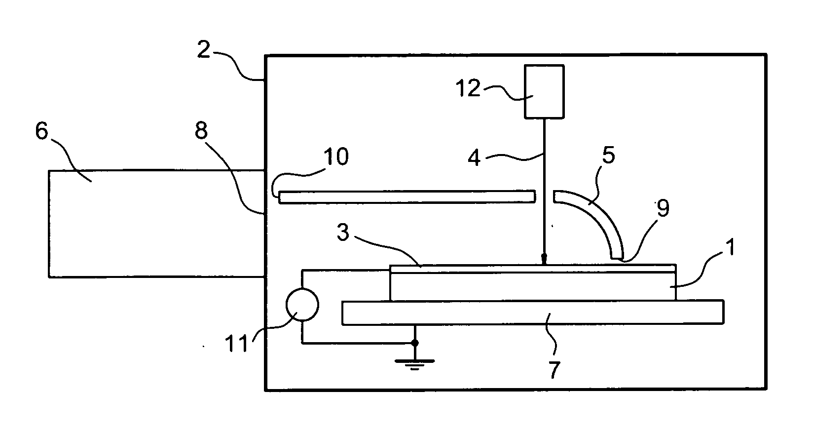
[0007] The faults engendered in the sub-layer by the polishing processes of the optical components produce notable drop in laser flux behaviour by absorbing the photons and trapping electrons and holes. These faults can be fissures terminating at the surface of incidence, metallic inclusions but likewise localised faults (oxygen gaps, liaison rupture, atomic impurities . . . ). The study of such localised faults is very delicate since the perturbed layer is extremely fine (of the order of several micrometers) and the faults are not observable by surface measuring techniques. When determining laser damage, in terms of the surface, it is a question of the surface as such and of the volume situated immediately under the surface, down to a depth which can reach several micrometers. The depth concerned is itself a function of the surface density of power of the laser to which the surface is going to be subjected.

[0008] The aim of the process according to the invention is to solve these ...


PUM


Abstract

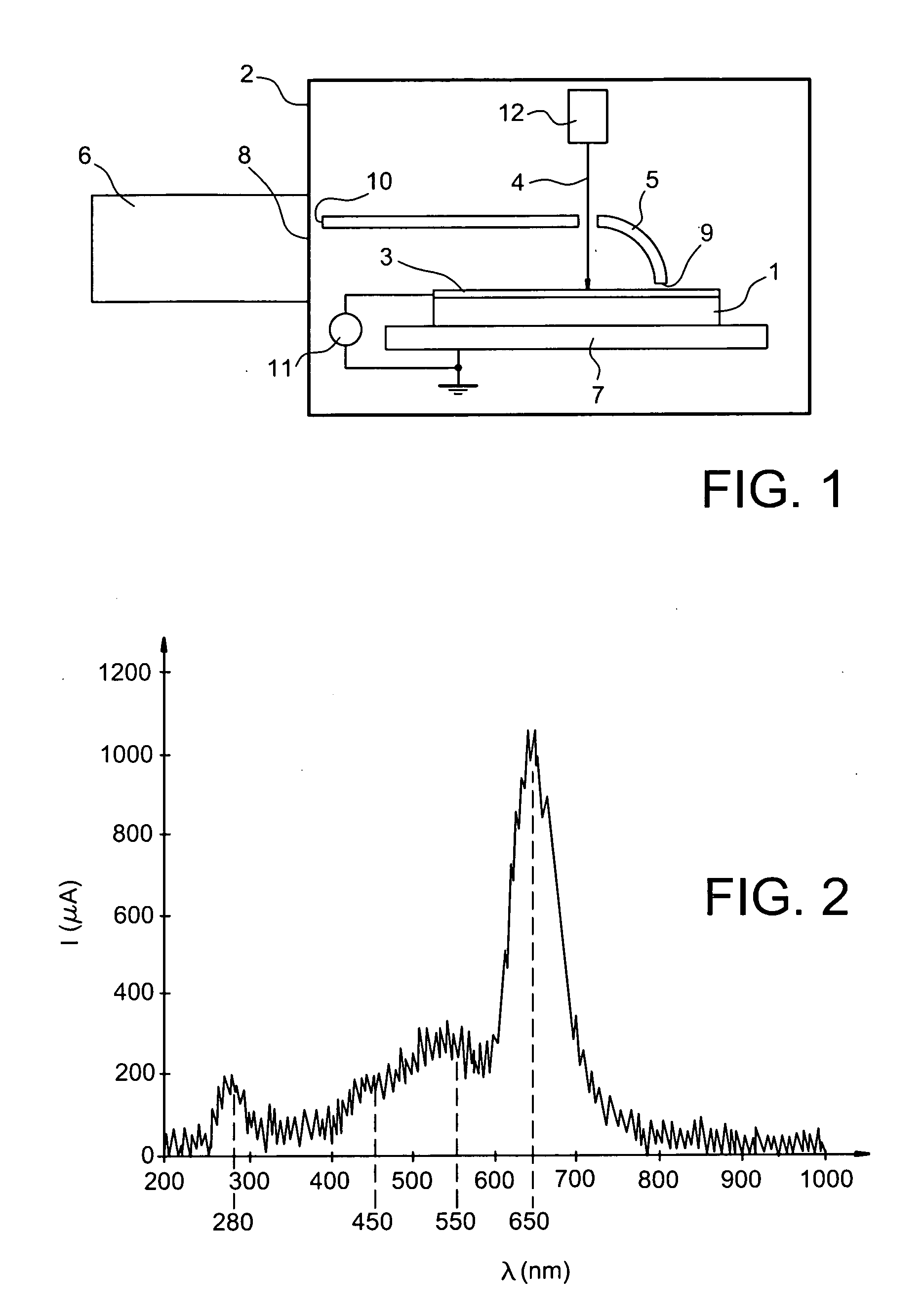
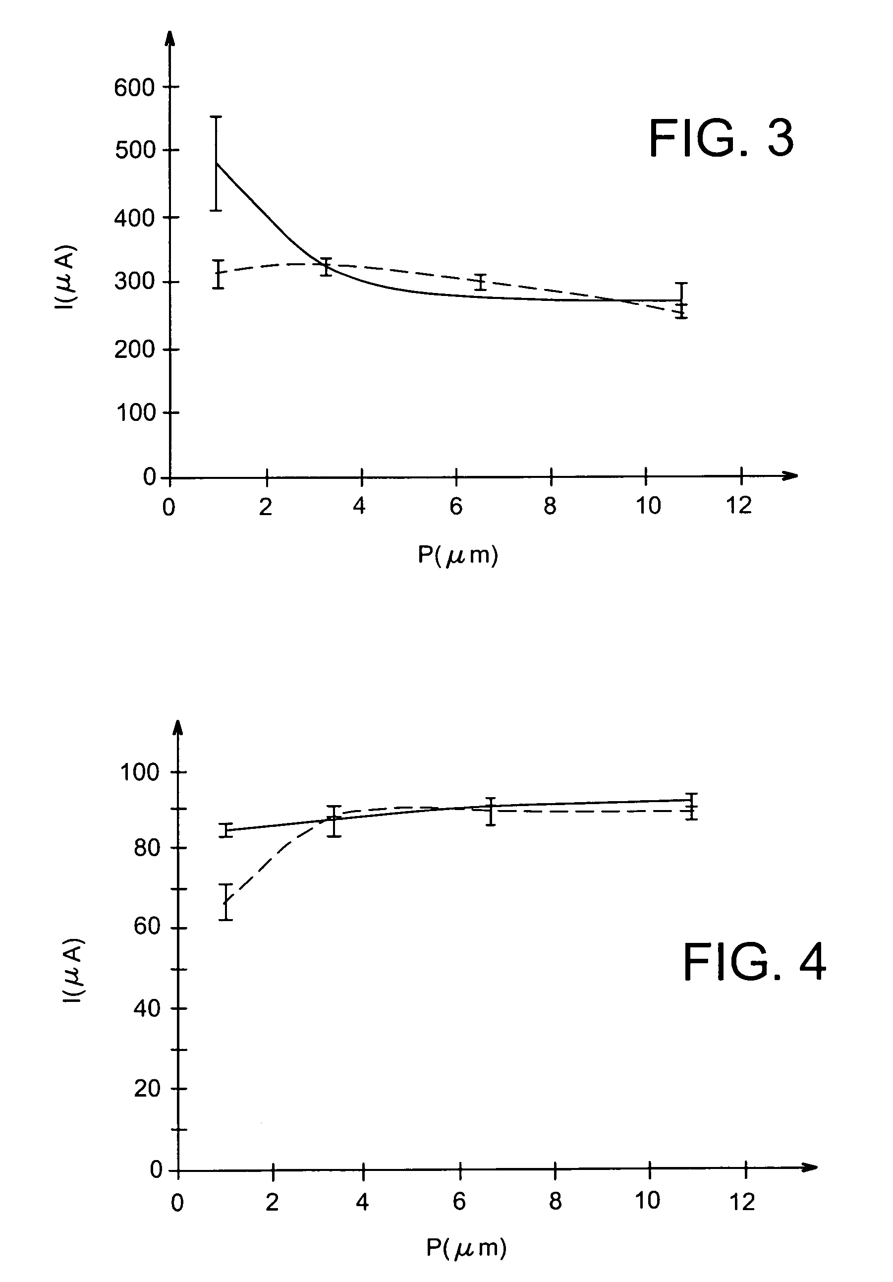
A predictive choice process of a manufacturing process of an optical component intended to be subjected to laser fluxes, the choice being intended to select from among several possible manufacturing processes that which results in components having better laser flux behaviour than those obtained by the other possible processes characterised in that a) a number N of cathodoluminescence measurements are made on components obtained by a first of the possible manufacturing processes, while the component receives an electronic beam having a determined energy, a focus on the surface of the determined component and a determined intensity controlled by a value of a ground current measured on the component, while it is being subjected to said electronic beam, b) an average cathodoluminescence value on the N measurements is calculated, c) operations a) and b) on components obtained by each of the other possible manufacturing processes are repeated, d) the most advantageous manufacturing process is decided as the one for which the average cathodoluminescence value is the lowest.

Description

TECHNICAL FIELD [0001] The invention relates to the field of non-destructive processes for measuring or comparing the laser flux behaviour of optical components. PRIOR ART [0002] The passage of a strong laser flux through the components of the chain of a very high-power laser (laser glasses, polarisers, mirrors, thin layers, crystals, cabin windows, etc.), or more generally of any optical component, causes the appearance of volume or surface damage to the components which progressively degrade the characteristics of the beam. [0003] The laser flux behaviour of the materials making up optical components is determined generally by taking laser shots at a sample and noting the variation in certain optical parameters (diffusion, absorption . . . ) or by directly observing the appearance of microscopic volume or surface damage of the materials. These measurements or observation help determine possible damage and determine whether or not the sample is suitable to support a laser flux of d...

Claims


Application Information

Patent Timeline
IPC IPC(8): G01R31/00G01M11/00
CPCG01M11/00
Inventor BIGARRE, JANICKHOURQUEBIE, PATRICKDOUCET, LUDOVIC
Owner COMMISSARIAT A LENERGIE ATOMIQUE ET AUX ENERGIES ALTERNATIVES
Why Eureka
Try Eureka