High-Speed Transceiver Tester Incorporating Jitter Injection

a transceiver and tester technology, applied in the direction of receiving signal processing, monitoring of receiving devices, instruments, etc., can solve the problems of unreliability, difficult to design, characterize and manufacture reliably, and difficulty in ensuring quality, etc., to achieve the effect of ensuring quality and ensuring reliability, and requiring test professionals to revise their quality assurance methodologies

Inactive Publication Date: 2007-05-17
DFT MICROSYST
View PDF84 Cites 24 Cited by
  • Summary
  • Abstract
  • Description
  • Claims
  • Application Information

AI Technical Summary

Benefits of technology

[0005] In one embodiment, the present disclosure is directed to a high-speed digital tester. The high-speed digital tester comprises a jitter generator that includes a multiplexer configured to receive a first clock input signal and a second clock input signal phased-shifted relative to the first clock input signal by a delay. The multiplexer has a mu

Problems solved by technology

This circuitry, however, is analog in nature and is generally hard to design, characterize, and manufacture reliably.
Accordingly, this unreliability creates challenges in the production test-phase.
These challenges are forcing test professionals to revise their quality-assurance methodologies.
These revisions, for example, include formulating new methodologies to screen modem high-speed transceiver designs because simple loop back testing is no longer sufficient.
These instruments, however, are rarely practical for production testi

Method used


Image

  • High-Speed Transceiver Tester Incorporating Jitter Injection
  • High-Speed Transceiver Tester Incorporating Jitter Injection
  • High-Speed Transceiver Tester Incorporating Jitter Injection

Examples


Embodiment Construction

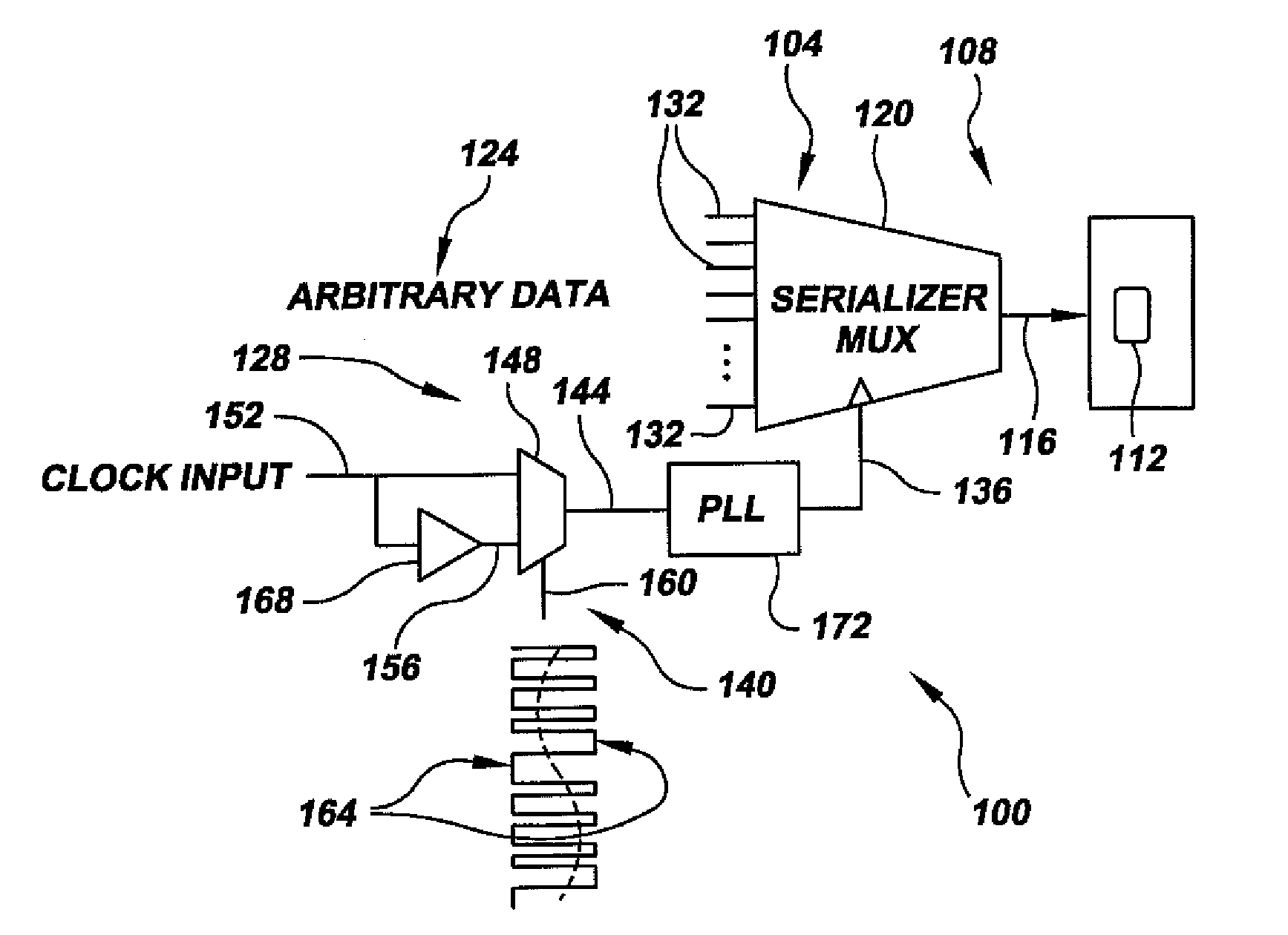
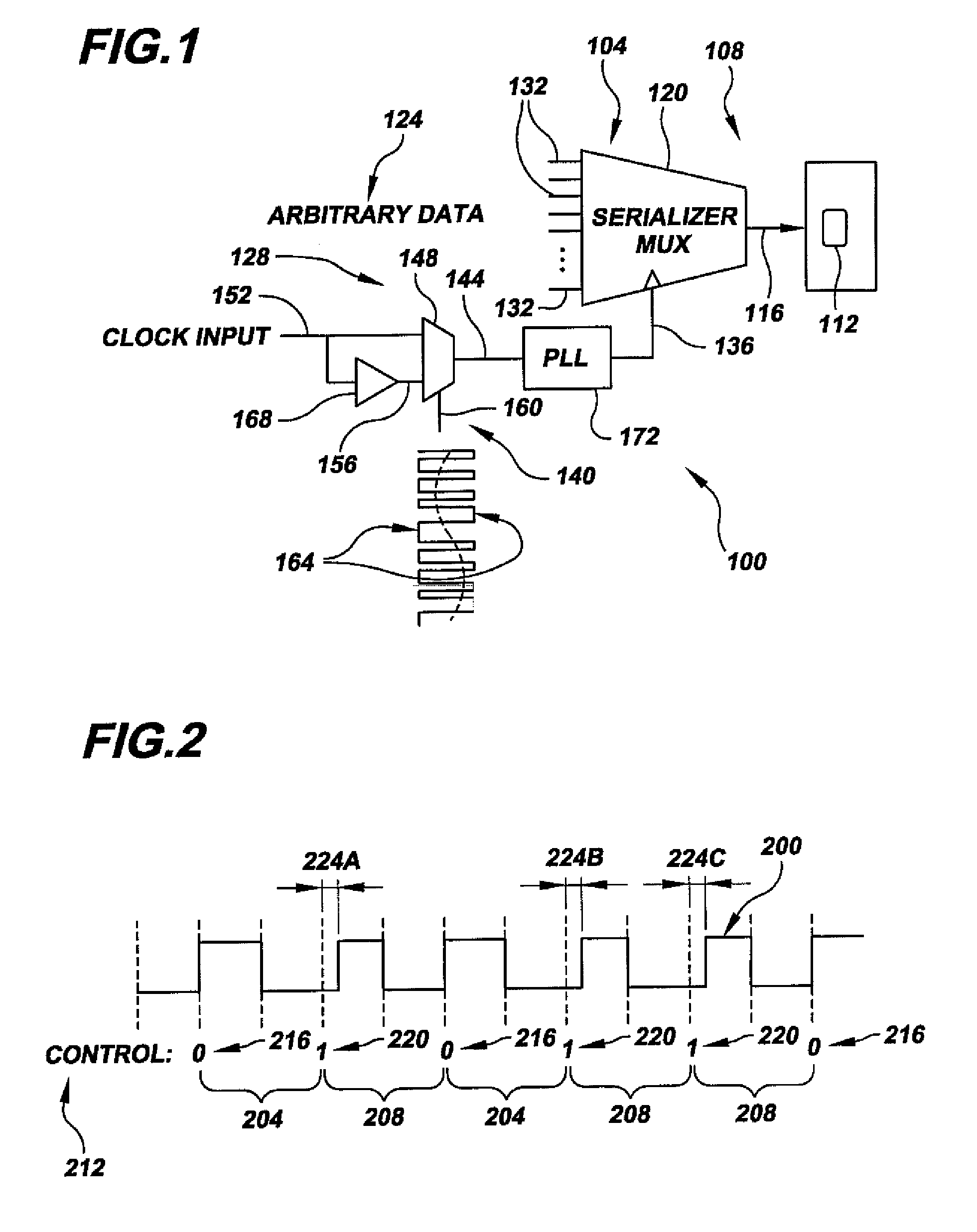
[0017] Referring now to the drawings, FIG. 1 illustrates a jitter-test setup 100 in accordance with a first embodiment of the present invention. At a high level, test setup 100 includes a high-speed tester 104 in communication with a one or more devices-under-test (DUTs), e.g., DUT 108, each comprising high-speed transceiver circuitry, such as transceiver circuitry 112. As described below in detail, tester 104 is configured for providing transceiver circuitry 112 with a high-speed jittered stimulus pattern (represented by arrow 116) for testing the transceiver circuitry's response to jittered input. As also described below, a useful feature of tester 104 is that the tester can be designed to generate jittered stimulus patterns, such as pattern 116, based on very small delays (generally limited fundamentally only by noise due to thermal agitation in semiconductor devices) using very simple hardware. As those having ordinary skill in the art will readily appreciate, DUT 108 may be vir...


PUM


Abstract

A tester for testing high-speed serial transceiver circuitry. The tester includes a jitter generator that uses a rapidly varying phase-selecting signal to select between two or more differently phased clock signals to generate a phase-modulated signal. The phase-selecting signal is designed to contain low-and high-frequency components. The phase-modulated signal is input into a phase filter to filter unwanted high-frequency components. The filtered output of the phase filter is input into a data-transmit serializer to serialize a low-speed parallel word into a high-speed jittered test pattern for input into the transceiver circuitry.

Description

RELATED APPLICATION DATA [0001] This application claims the benefit of priority of U.S. Provisional Patent Application Ser. No. 60 / 730,633, filed Oct. 27, 2005, and titled “High-Speed Transceiver Tester Incorporating Jitter Injection,” that is incorporated by reference herein in its entirety.FIELD OF THE INVENTION [0002] The present invention generally relates to the field of integrated circuit testing. In particular, the present invention is directed to a high-speed transceiver tester incorporating jitter injection. BACKGROUND OF THE INVENTION [0003] High-speed transceiver circuitry is finding widespread use in the microelectronics and computer industries because of its superior traits over conventional bus technologies. These traits include, without limitation, improved throughput and wiring efficiencies. This circuitry, however, is analog in nature and is generally hard to design, characterize, and manufacture reliably. Accordingly, this unreliability creates challenges in the pr...

Claims


Application Information

Patent Timeline
IPC IPC(8): G11B20/20G06K5/04G11B5/00
CPCG01R31/31709H04B17/20H04B17/15
Inventor HAFED, MOHAMED M.LABERGE, SEBASTIENPISHDAD, BARDIATAM, CLARENCE K. L.
Owner DFT MICROSYST
Why Eureka
Try Eureka