Reference feature design for flare location monitor in perpendicular write pole process

a technology of reference feature design and flare location, which is applied in the direction of manufacturing head surfaces, instruments, manufacturing tools, etc., can solve the problem of not being able to serve as a coordination reference poin

Inactive Publication Date: 2007-05-24
WESTERN DIGITAL TECH INC
View PDF6 Cites 15 Cited by
  • Summary
  • Abstract
  • Description
  • Claims
  • Application Information

AI Technical Summary

Benefits of technology

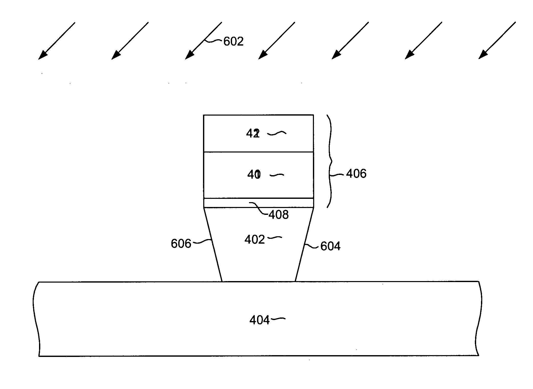
[0009] The reference feature pair can be configured as narrow line features. For example, if the ion mill process mills the pole to have mirror symmetry about the y axis only, the reference feature pair can be configured in a way that the dimension in y is much larger than that in x. During ion mill, the edges parallel to the y direction receive equal amount time of milling, because the edge dimension in x is comparatively small, the tips of the features will erode in the same amount so that the center location of the tips will not change after mill.

Problems solved by technology

As a result of this, the geometrical center of these features will no longer be “stationary” and thus cannot be served as a coordination reference point.

Method used


Image

  • Reference feature design for flare location monitor in perpendicular write pole process
  • Reference feature design for flare location monitor in perpendicular write pole process
  • Reference feature design for flare location monitor in perpendicular write pole process

Examples


Embodiment Construction

[0020] The following description is the best embodiment presently contemplated for carrying out this invention. This description is made for the purpose of illustrating the general principles of this invention and is not meant to limit the inventive concepts claimed herein.

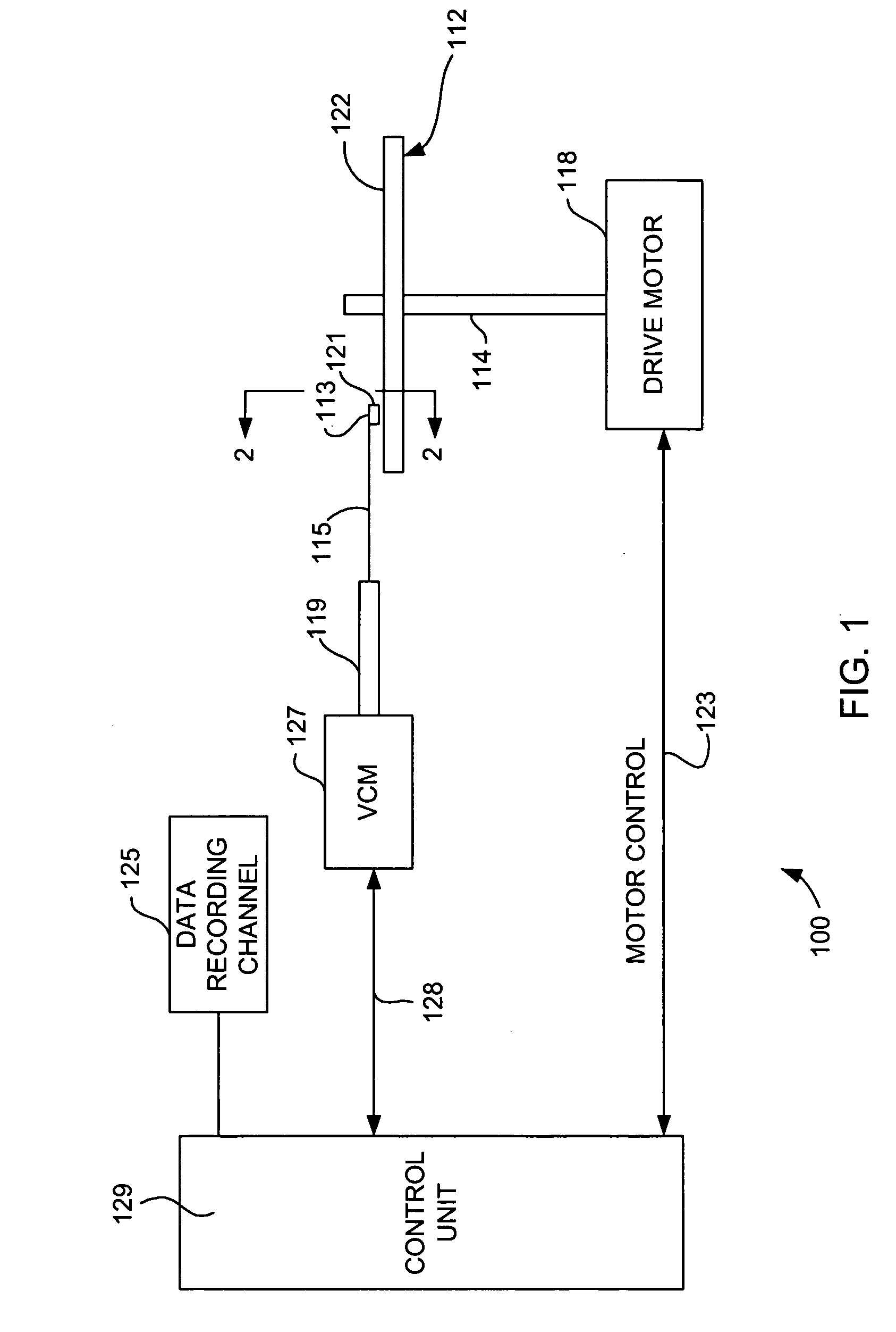
[0021] Referring now to FIG. 1, there is shown a disk drive 100 embodying this invention. As shown in FIG. 1, at least one rotatable magnetic disk 112 is supported on a spindle 114 and rotated by a disk drive motor 118. The magnetic recording on each disk is in the form of an annular pattern of concentric data tracks (not shown) on the magnetic disk 112.

[0022] At least one slider 121 is positioned near the magnetic disk 112, each head gimble assembly 113 supporting one or more magnetic heads 121. As the magnetic disk rotates, the head gimble assembly 113 swings in and out over the disk surface 122 so that the magnetic head 121 may access different tracks of the magnetic disk where desired data are written. Each ...


PUM

PropertyMeasurementUnit
angleaaaaaaaaaa
angleaaaaaaaaaa
angleaaaaaaaaaa

Abstract

A method for measuring recession in a wafer undergoing an asymmetrical ion mill process. The method includes the formation of first and second reference features and possibly a dummy feature. The reference features are constructed such that the location of the midpoint between them is unaffected by the asymmetrical ion mill. By measuring the distance between a portion of the dummy feature and the midpoint between the reference features, the amount of recession of the dummy feature can be measured. The measurement can be used to calculate the relative location of the flare to the read sensor rear edge through overlay information. The reference features can be constructed as a pair of isosceles triangles with apexes that face one another. By keeping the angles of the sides of the features steep (ie. nearly parallel with the direction in which the ion mill is asymmetrical) the amount of material consumed on each of the reference features is substantially equal and the midpoint between the reference features is substantially stationary.

Description

FIELD OF THE INVENTION [0001] The present invention relates to the process control aspect of the manufacture of thin film magnetic heads and more particularly to a metrology methodology for determining a flare point location and referencing it to a previously built read sensor layer during manufacture of a magnetic write element. BACKGROUND OF THE INVENTION [0002] One of the most important components of a computer is the magnetic disk drive. The hard drive includes magnetic disks and sliders where the magnetic head assembly including write and read heads are mounted, the suspension arms accommodating them, and an actuator arm, and the related controlling circuitry. When the magnetic disks rotate, air adjacent to the disk surface moves with them. This allows the sliders, i.e., the individual magnetic heads, to fly on an extremely thin cushion layer of air, generally referred to as an air bearing. When the slider flies on the air bearing, the actuator arm swings the suspension arm to ...

Claims


Application Information

Patent Timeline
Patent Type & Authority Applications(United States)
IPC IPC(8): G11B5/127C23C14/00
CPCG11B5/1278G11B5/3163Y10T29/49046Y10T29/49041Y10T29/49052Y10T29/49048Y10T29/49043
Inventor DULAY, SUKHBIR SINGHHWU, JUSTIN JIA-JENPHAM, THAO JOHN
Owner WESTERN DIGITAL TECH INC
Why Eureka
Try Eureka