Conserving components of fluids

a technology of fluids and components, applied in the direction of filtration separation, separation process, borehole/well accessories, etc., to achieve the effect of greater control

Inactive Publication Date: 2007-05-24
TOTAL SEPARATION SOLUTIONS
View PDF20 Cites 9 Cited by
  • Summary
  • Abstract
  • Description
  • Claims
  • Application Information

AI Technical Summary

Benefits of technology

[0011] Unlike a conventional distillation process, the SPR preserves the ratios of the cations and anions, as well as the solids, to each other in the solution that enters the SPR, while facilitating the removal of water. A conventional distillation process would tend to scale out some of the constituents in more or less difficultly predictable portions and relationships. The fact that in our process the ratios of the non-aqueous components remain essentially the same can be used to provide greater control over the process of reconstituting oil well completion and workover fluids. Either before or after passing through the SPR, the solution may be treated with additives to restore the original density, crystallization temperature, or balance of cations and anions, or to adjust the individual concentrations of components to respond to new conditions found in the well. Since the operator may rely on the SPR to preserve the ratios of the solid and dissolved components to each other in the fluid that enters the SPR, any distortion of the ratios caused by the formation or wellbore can be adjusted or compensated for either before the fluid enters the SPR or after it leaves, without concern for a further distortion of the ratios caused by the SPR. This would not be the case with any device or process step that might result in scaling. If the conserved components are to be used in a different well requiring different ratios of components to each other, the operator again may rely on the SPR not to alter the existing ratios, and make any necessary adjustments accordingly.
[0012] Definition: We use the term “cavitation device,” or “SPR,” to mean and include any device which will impart thermal energy to flowing liquid by causing bubbles or pockets of partial vacuum to form within the liquid it processes, the bubbles or pocke

Problems solved by technology

A conventional distillation process would tend to scale out some of the constituents in more or less difficultly predict

Method used


Image

  • Conserving components of fluids
  • Conserving components of fluids
  • Conserving components of fluids

Examples


example

Oil Mud Emulsion

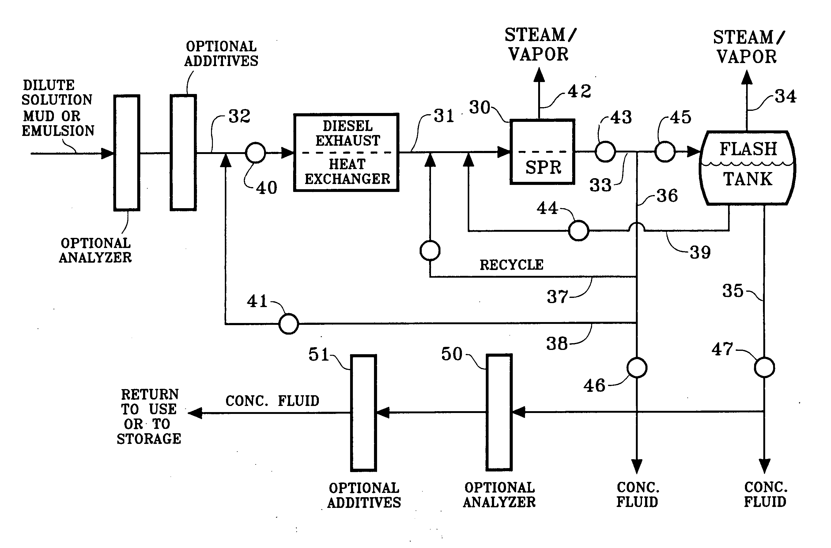
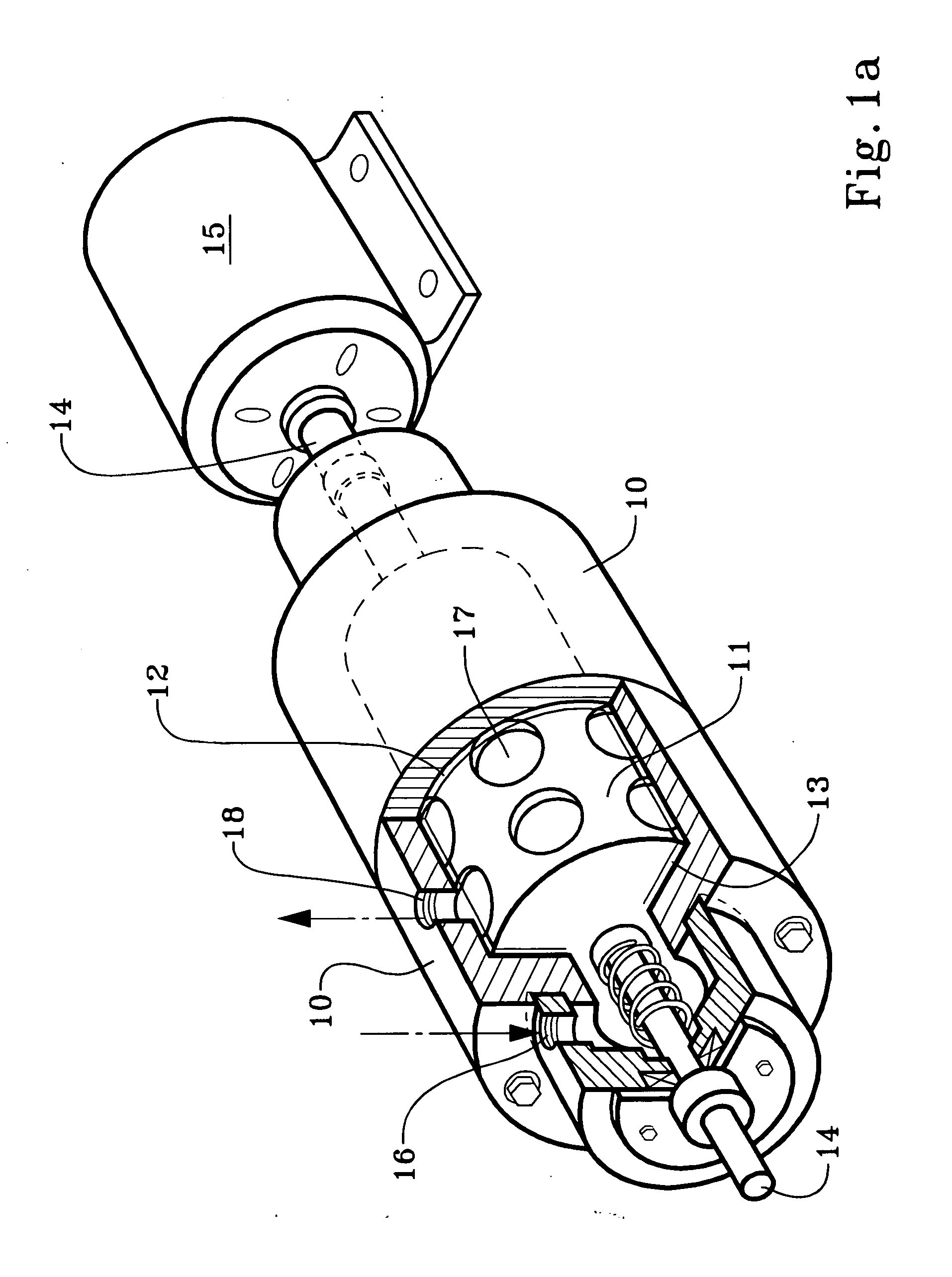
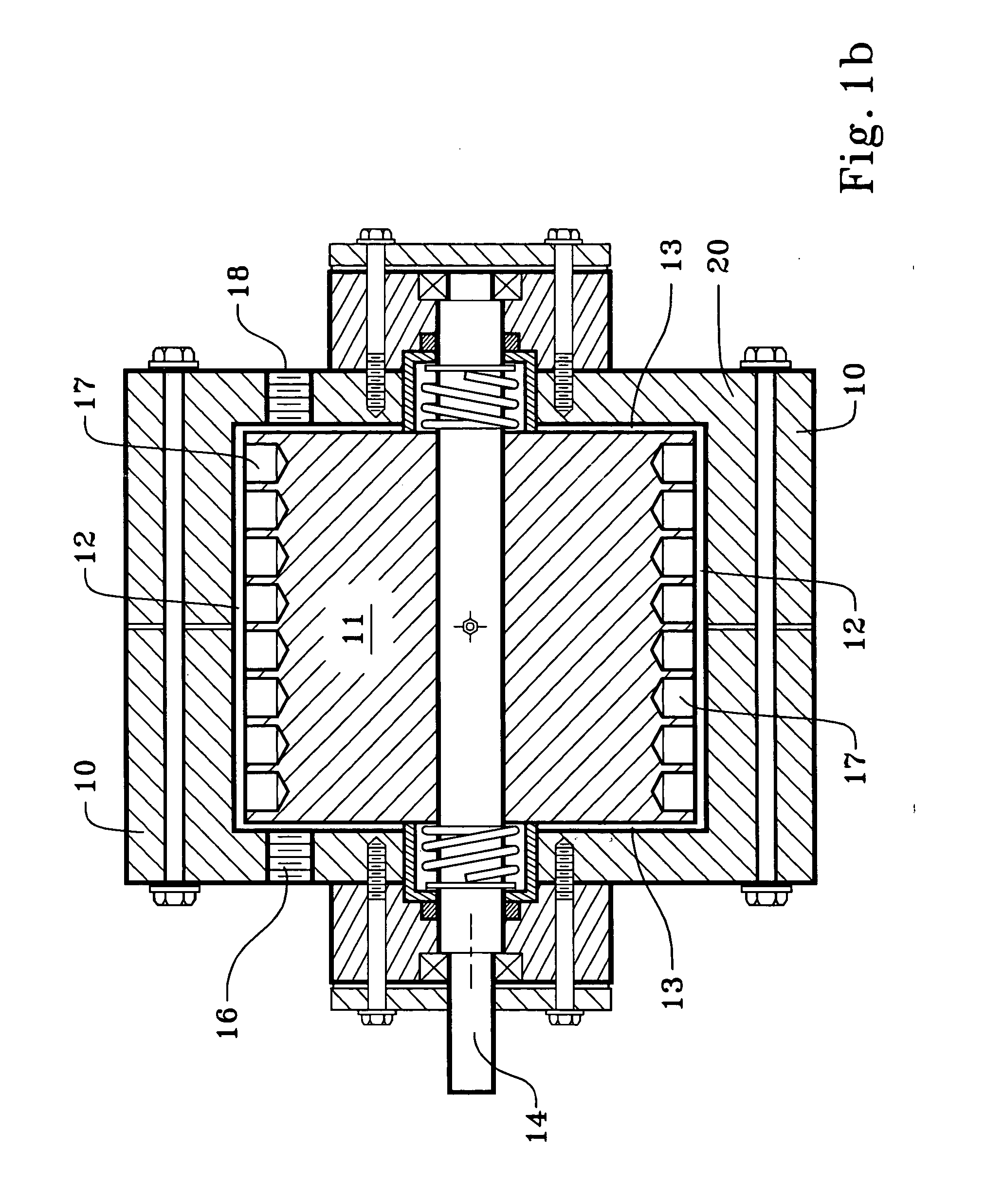
[0035] Using a 15″ by 2″ cavitation device, ten gallons of oil mud emulsion were treated to remove water. Initially the oil mud emulsion contained 18% water by volume, the balance being oil and solids typical of an oil well mud. The oil mud emulsion was sent through the cavitation device operating at 3600 RPM and recycled through the tank, which rapidly increased the temperature of the oil mud emulsion from room temperature to 240° F. Once that temperature was reached, the RPM of the cavitation device was controlled automatically in order to maintain an outlet temperature 240° F. At equilibrium, while recirculating the material and continuing to recycle through the tank, the speed was maintained at 1700 RPM, requiring about 13.5 HP. At 15 minutes, the material contained 13% water; at 30 minutes, it contained 10% water, and at 45 minutes the water was reduced to 5% by volume. Essentially none of the oil was evaporated

[0036] Thus our invention is seen to include a me...


PUM

PropertyMeasurementUnit
Fractionaaaaaaaaaa
Fractionaaaaaaaaaa
Fractionaaaaaaaaaa

Abstract

A cavitation device is used to heat, concentrate and recycle or otherwise reuse dilute and other oil well fluids, brines and muds, and solution mining fluids, all of which commonly contain ingredients worthy of conservation. The cavitation device can be powered by a Diesel engine whose exhaust may be used to heat the incoming fluid, and the product of the cavitation device is directed to a flash tank.

Description

RELATED APPLICATION [0001] This application claims the full benefit of copending application Ser. No. 11 / 352,889, filed Feb. 13, 2006, which in turn claims the benefit of provisional applications Ser. No. 60 / 652,549 filed Feb. 14, 2005 and 60 / 652,711 filed Feb. 14, 2005.TECHNICAL FIELD [0002] A cavitation device is used to concentrate and recycle or otherwise reuse oil well fluids and muds, solution mining fluids, and industrial oil / water emulsions, all of which commonly contain ingredients worthy of conservation. BACKGROUND OF THE INVENTION [0003] In oil and other hydrocarbon production, drilling, completion and workover, fluids are typically circulated down the string of tubes and upwards around the outside of the tubes, contacting the formation surface of the wellbore from which the hydrocarbons are to be produced. In the case of a completion or workover fluids an original clear brine is typically prescribed to have a density which is a function of the formation pressure. The sal...

Claims


Application Information

Patent Timeline
IPC IPC(8): E21B43/40E21B21/06B01D17/06B01D35/18
CPCE21B21/063Y10S507/904
Inventor SMITH, KEVIN W.SLOAN, ROBERT L.SMITH, HARRY D. JR.
Owner TOTAL SEPARATION SOLUTIONS
Why Eureka
Try Eureka