Selective naphtha hydrodesulfurization with high temperature mercaptan decomposition

a technology of mercaptan decomposition and hydrodesulfurization, which is applied in the petroleum industry, hydrotreatment process, hydrocarbon oil treatment, etc., can solve the problems of unfavorable loss of olefins through hydrogenation, increase the complexity of overall refinery operations, and add significantly to production costs

Inactive Publication Date: 2007-05-24
EXXON RES & ENG CO
View PDF2 Cites 59 Cited by
  • Summary
  • Abstract
  • Description
  • Claims
  • Application Information

AI Technical Summary

Benefits of technology

[0022] In still another preferred embodiment, the total sulfur content of said mercaptan decomposition reactor product stream is less than about 1 wt. % of the total sulfur content of said olefinic naphtha feedstream.
[0023

Problems solved by technology

Hydrodesulfurization of cracked naphthas using conventional naphtha desulfurization catalysts under conventional startup procedures and under conventional conditions required for sulfur removal, typically leads to an undesirable loss of olefins through hydrogenation.
Such additional refining, or course, adds significantly to production costs.
Although selective hydrodesulfurization processes have been developed to avoid

Method used


Image

  • Selective naphtha hydrodesulfurization with high temperature mercaptan decomposition
  • Selective naphtha hydrodesulfurization with high temperature mercaptan decomposition

Examples


example 1

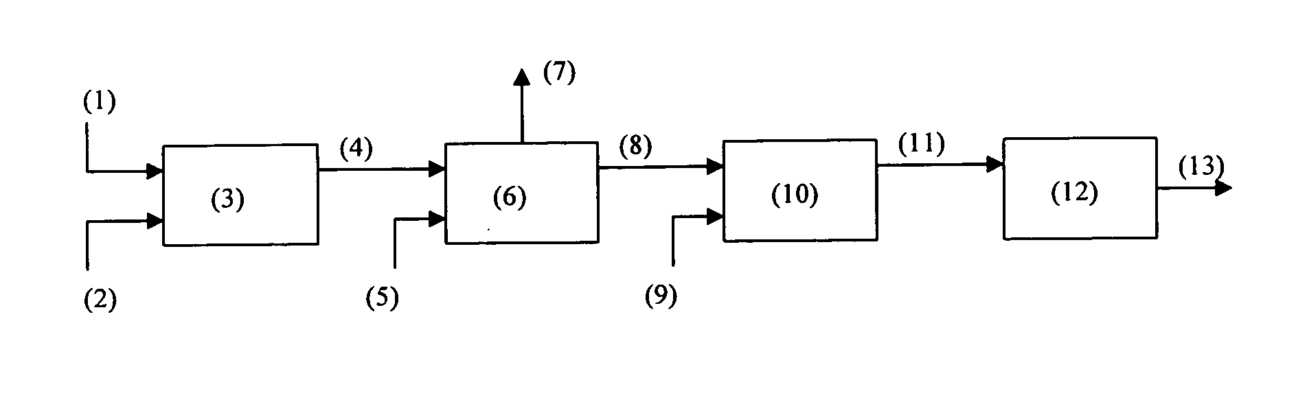
[0043] In this example, the process configuration utilized is shown in FIG. 1. The hydrogen treat gas rates, shown as streams (2) and (9) in FIG. 1, are 2,000 standard cubic feet per barrel (scf / b). The amount of H2S removal in the H2S reaction zone (6) is modeled utilizing an H2S removal step to remove free and dissolved H2S from the process stream at the first hydrodesulfurization reaction pressures (327 psig). Any stripping agent utilized in the art to facilitate H2S removal, such as steam or an amine solution, can be utilized and is shown as stream (5). The H2S or H2S rich compound is then removed from the process via stream (7). The conditions and resulting product qualities are predicted based on a kinetic model developed from a pilot plant database are shown in Tables 1 and 2 below.

TABLE 11st HDS2nd HDSMercaptan RemovalStageStageStage(3)(10)(12)Temperature (° F.)535525625Pressure (psig)327327327

[0044]

TABLE 2FirstSecondThirdReactorStrippedReactorReactorOlefinicEffluentEfflue...

example 2

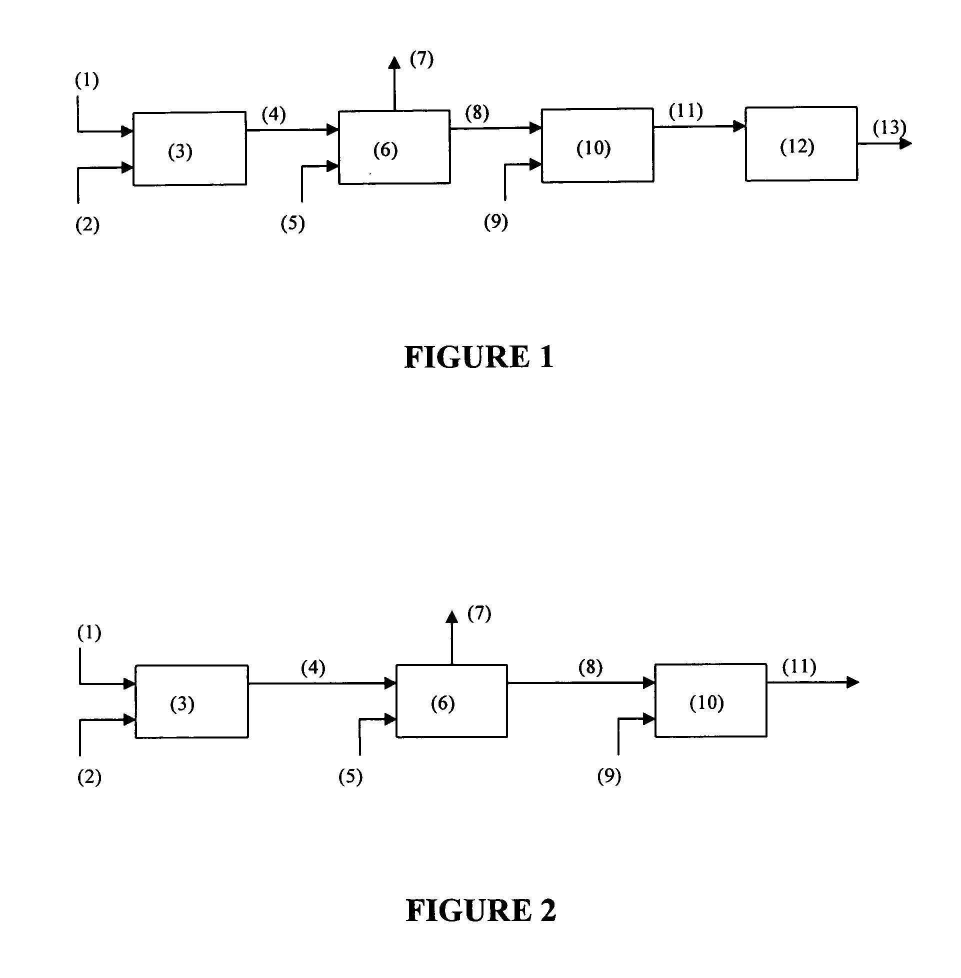
[0045] In this example, the process configuration utilized is shown in FIG. 2. The hydrogen treat gas rates, shown as streams (2) and (9) in FIG. 2, are 2,000 standard cubic feet per barrel (scf / b). The amount of H2S removal in the H2S reaction zone (6) is modeled utilizing an H2S removal step to remove free and dissolved H2S from the process stream at the hydrodesulfurization reaction pressures (327 psig). Any stripping agent utilized in the art to facilitate H2S removal, such as steam or an amine solution, can be utilized and is shown as stream (5). The H2S or H2S rich compound is then removed from the process via stream (7). The conditions and resulting product qualities are predicted based on a kinetic model developed from a pilot plant database are shown in Tables 3 and 4 below.

TABLE 31st HDSMercaptan RemovalStageStage(3)(12)Temperature (° F.)535625Pressure (psig)327327

[0046]

TABLE 4FirstSecondReactorStrippedReactorOlefinicEffluentEffluentProductFeedstreamStreamStreamStream(1)...


PUM


Abstract

A process for the selective hydrodesulfurization of olefinic naphtha streams containing a substantial amount of organically bound sulfur and olefins. The olefinic naphtha stream is selectively desulfurized in a first hydrodesulfurization reaction stage. This effluent stream is then contacted with a stripping agent in a H2S removal zone, such as steam or an amine solution, to remove H2S from the effluent stream, thereby reducing the H2S partial pressure of the process stream. The process stream is then subjected to a second desulfurization reaction stage followed by a mercaptan decomposition stage to reduce the content of mercaptan sulfur in the final product stream. In a second embodiment, the effluent stream from the first hydrodesulfurization reaction stage, after being subjected to the H2S removal zone, is fed directly to the mercaptan decomposition stage where total sulfur content and mercaptan sulfur content are reduced in the final product stream.

Description

FIELD OF THE INVENTION [0001] The present invention relates to a multistage process for the selective hydrodesulfurization and mercaptan removal of an olefinic naphtha stream containing a substantial amount of organically bound sulfur and olefins. BACKGROUND OF THE INVENTION [0002] Environmentally driven regulatory pressure concerning motor gasoline (“mogas”) sulfur levels have resulted in the widespread production of less than 50 wppm sulfur mogas in 2004, and levels below 10 wppm are being considered for later years. In general, this will require deep desulfurization of refinery naphtha streams. The largest target of naphtha streams for such processes are those resulting from cracking operations, particularly those from a fluidized catalytic cracking unit which comprise a large volume of the available refinery blending stock as well as generally higher sulfur content than the “non-cracked” refinery naphtha streams. Naphthas from a fluidized catalytic cracking unit (“cat naphthas”)...

Claims


Application Information

Patent Timeline
IPC IPC(8): C10G45/00C10G17/00
CPCC10G65/04C10G67/02C10G69/02C10G2300/1044C10G2300/202C10G2300/207C10G2300/301C10G2300/4006C10G2300/4012C10G2300/807
Inventor GREELEY, JOHN P.ELLIS, EDWARD S.HALBERT, THOMAS R.TRACY, WILLIAM J. IIIDYSARD, JEFFREY M.
Owner EXXON RES & ENG CO
Why Eureka
Try Eureka