

Light source driver circuit
a driver circuit and light source technology, applied in the direction of light sources, instruments, electrical devices, etc., can solve the problems of high cost and difficulty in making such dc input inverters, and achieve the effect of avoiding high cost and high power conversion efficiency
- Summary
- Abstract
- Description
- Claims
- Application Information
AI Technical Summary
Benefits of technology
Problems solved by technology
Method used
Image

Examples
Embodiment Construction
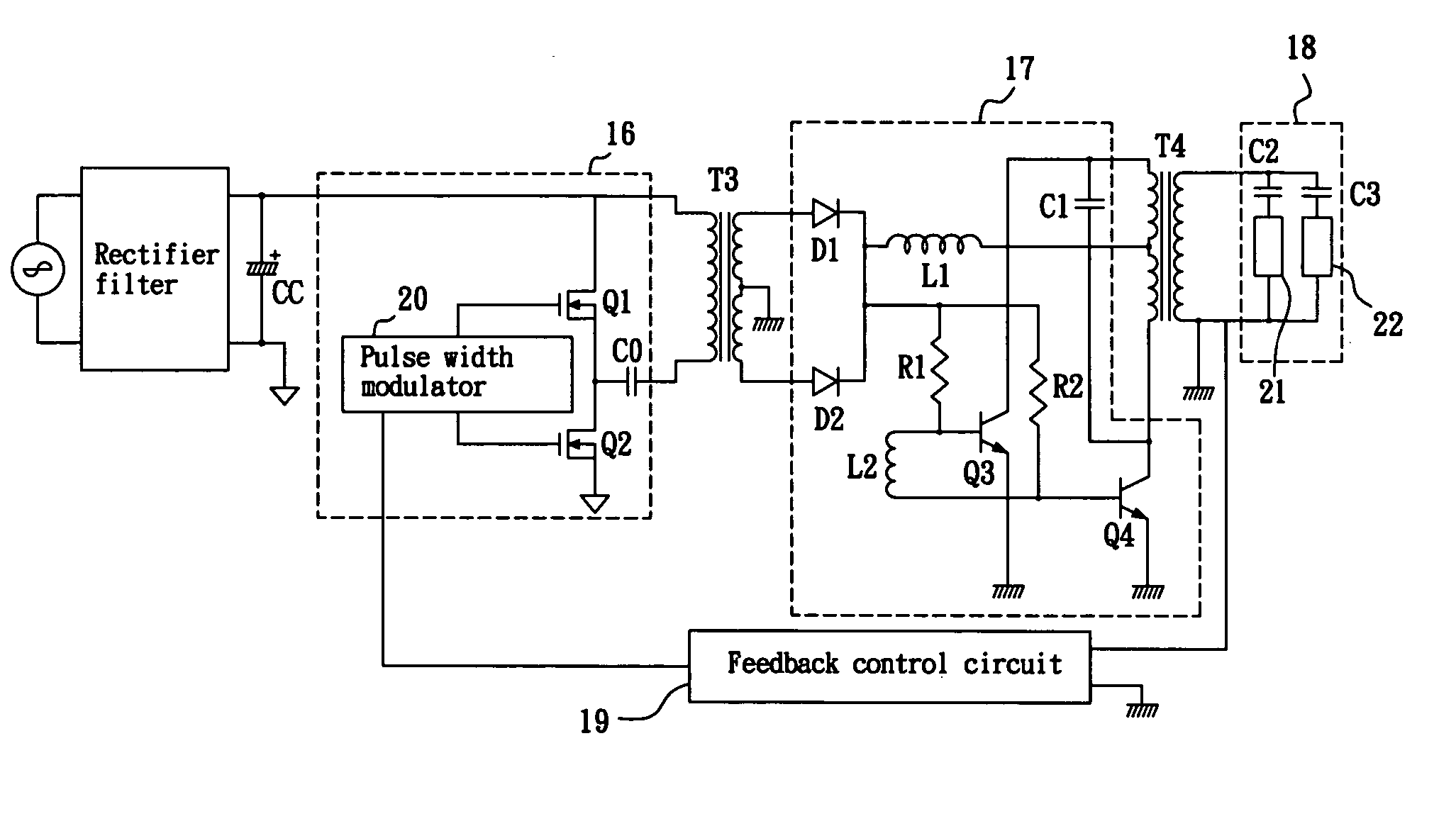
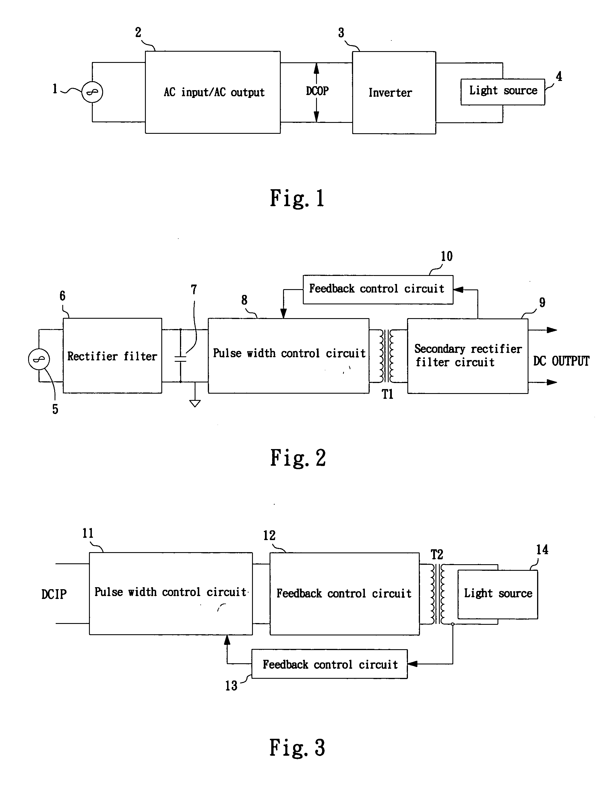
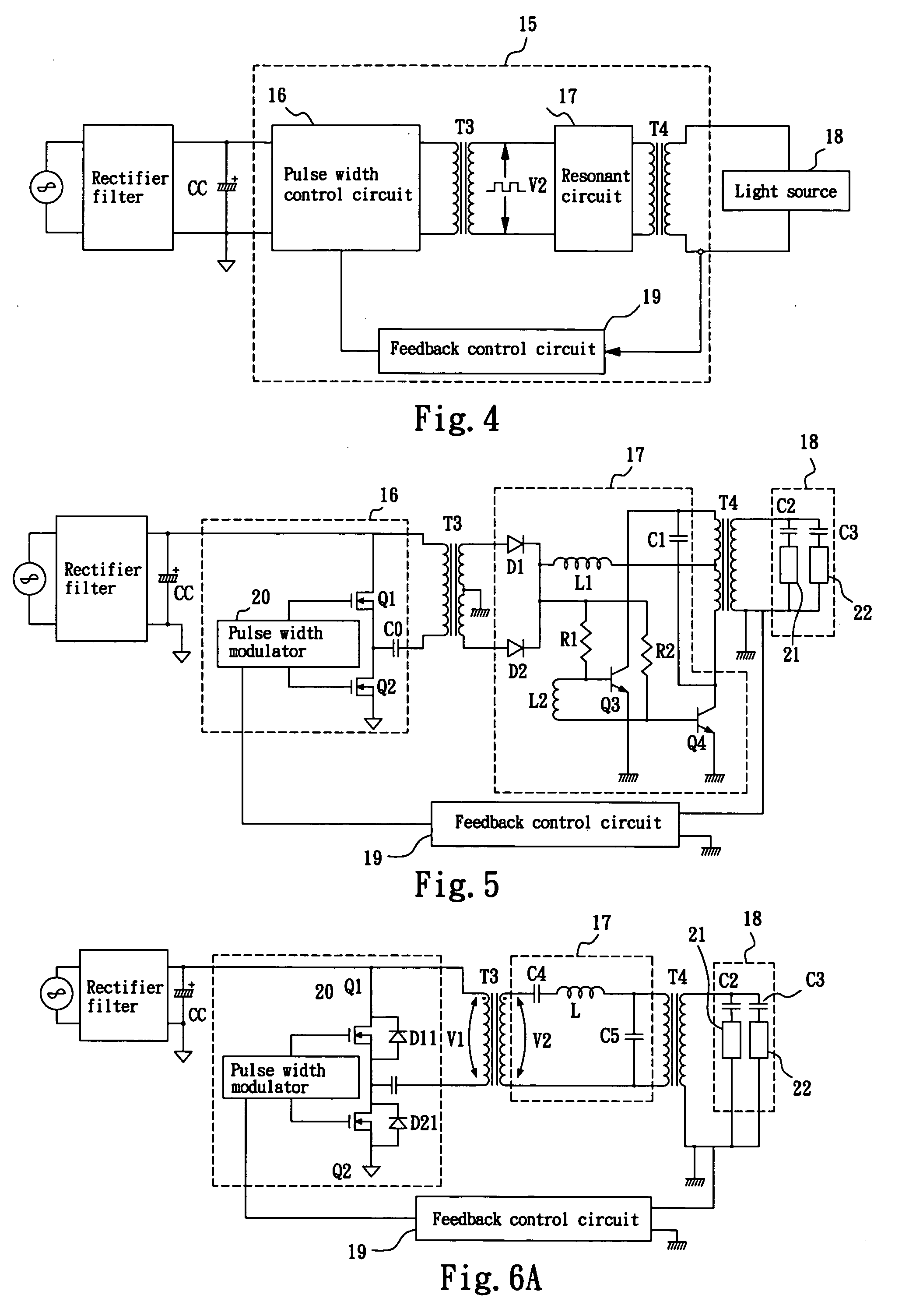
[0018] Referring to FIG. 4 for the schematic diagram of a light source driver circuit according to a first preferred embodiment of the present invention, the light source driver circuit 15 comprises a pulse width control circuit 16 that uses an AC power supply to produce a square wave, and the AC power supply could be city electricity passing through a rectifier filter circuit having a rectifier filter and a rectifier capacitor CC; a first transformer T3 having its primary winding for inputting the square wave and its secondary winding for outputting a transformation square wave V2; a resonant circuit 17 for inputting the transformation square wave V2 to produce a resonant sine wave; a second transformer T4 having its primary winding for inputting the resonant sine wave and its secondary winding for outputting a transformation sine wave to drive the light source device 18, and the light source device 18 could be a light source of an LCD backlight module; and a feedback control circu...
PUM
 Abstract
Description
Claims
Application Information