Luminance control apparatus for light emitting device

Inactive Publication Date: 2007-05-24
DENSO CORP
View PDF2 Cites 29 Cited by
  • Summary
  • Abstract
  • Description
  • Claims
  • Application Information

AI Technical Summary

Benefits of technology

[0013] The present invention therefore has an object to provide a luminance control apparatus for a light emitting device, the

Problems solved by technology

Therefore, it is difficult to control the luminance without changing the hue of the emitted light in the case of the current control.
This results in increased costs.
This variation in the luminance control cycle period may cause imbalance between the image display cycle period of a display screen and the luminance control cycle period of the backlight.
As a result, noises may appear on t

Method used


Image

  • Luminance control apparatus for light emitting device
  • Luminance control apparatus for light emitting device
  • Luminance control apparatus for light emitting device

Examples


Embodiment Construction

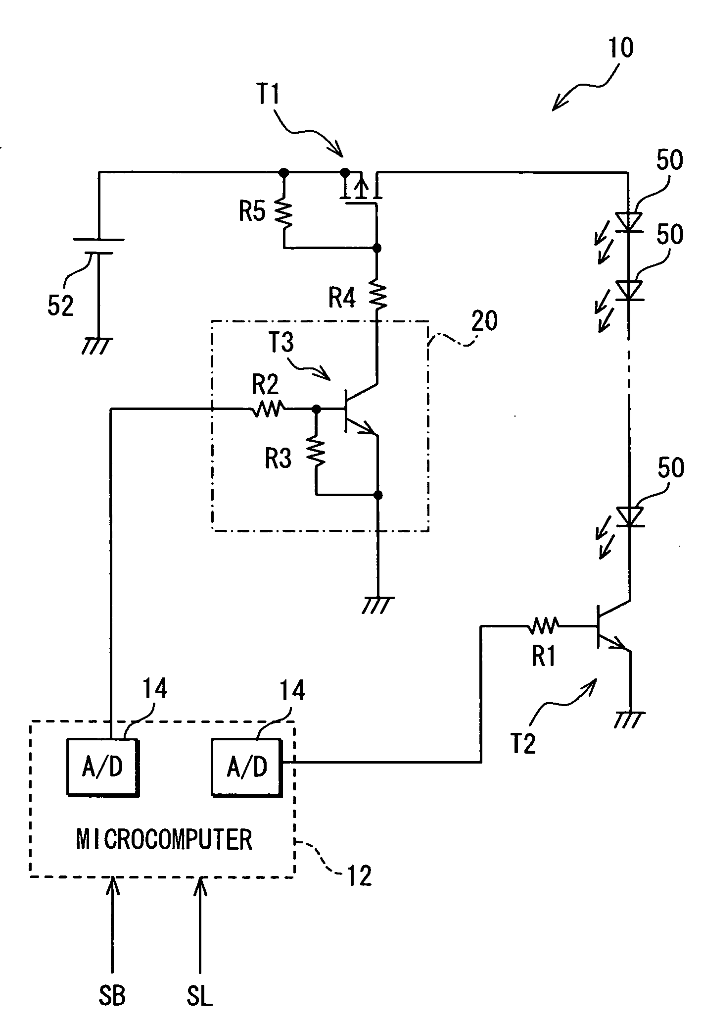
[0019] Referring to FIG. 1, a luminance control apparatus 10 is constructed to control a luminance of series-connected light emitting diodes (LEDs) as a light emitting device 50. The LEDs may be connected in parallel in part. The device 50 is used as a backlight of a liquid crystal display device for a vehicle.

[0020] The apparatus 10 is constructed with a first transistor T1, a second transistor T2, a microcomputer 12 and a driver circuit 20. The first transistor T1 is a normally-off type P-MOSFET and operates as a switching device. The source and the drain of the FET are connected to a vehicle battery 52 and the light emitting device 50, respectively. The second transistor T2 is a bipolar type. The collector, the emitter and the base are connected to the light emitting device 50, the ground and the microcomputer 12 through a resistor R1, respectively.

[0021] The driver circuit T3 includes a third transistor T3, which is a bipolar type, a resistor R2 and a resistor R3. The resistor...


PUM


Abstract

A luminance control apparatus for a backlight of a display device in a vehicle has a first transistor and a second transistor connected to the backlight. The first transistor is controlled by pulse-width modulation control, and the second transistor is controlled to supply a low level current at nighttime and a high level current at daytime under a condition that the first transistor is ON. The duty ratio of the first transistor is varied over a full range from 0% to 100% at the nighttime, while the duty ratio of the same is varied only in a partial range at the daytime.

Description

CROSS REFERENCE TO RELATED APPLICATION [0001] This application is based on and incorporates herein by reference Japanese Patent Application No. 2005-338757 filed on Nov. 24, 2005. FIELD OF THE INVENTION [0002] The present invention relates to a luminance control apparatus for a light emitting device and, more particularly, to an apparatus that improves luminance resolution of a light emitting device. BACKGROUND OF THE INVENTION [0003] As one method for controlling a luminance of a light emitting device such as a light emitting diode, a current supplied to the light emitting device is increased or decreased as disclosed in JP 2004-281922A. This current control is used for light emitting diodes used as a backlight of a liquid crystal display. In this current control, a brightness detecting device is provided to detect brightness of a surrounding area, and the backlight (light emitting diodes) is driven to emit more light as the detected brightness increases. The amount of light emissi...

Claims


Application Information

Patent Timeline
IPC IPC(8): G09G3/14B60K35/00H01L33/00H05B37/02
CPCG09G3/3406G09G2320/0633G09G2320/064H05B33/0845H05B45/10
Inventor MAEJIMA, YASUSHI
Owner DENSO CORP
Why Eureka
Try Eureka