Supercharge Your Innovation With Domain-Expert AI Agents!

Optical apparatus, method of determining position of optical element in optical system, and device manufacturing method

a technology of optical elements and optical apparatuses, applied in the direction of photomechanical apparatuses, instruments, optical elements, etc., can solve the problems of inability to calculate optimal adjustment amounts for various aberrations, and the change in wavefront aberration, one of the most important aberrations, cannot be expressed

Inactive Publication Date: 2007-05-24
CANON KK
View PDF4 Cites 8 Cited by
  • Summary
  • Abstract
  • Description
  • Claims
  • Application Information

AI Technical Summary

Benefits of technology

This approach allows for effective minimization of aberrations, including wavefront aberration, by optimizing the adjustment of optical elements, ensuring balanced correction across various image heights, thereby improving the overall performance of the optical system.

Problems solved by technology

However, a change in wavefront aberration which is one of important aberrations cannot be expressed as the linear function of the adjustment amount of each part.
The method disclosed in Japanese Patent Laid-Open No. 2002-367886 cannot calculate optimal adjustment amounts for various aberrations including the wavefront aberration.

Method used


Image

  • Optical apparatus, method of determining position of optical element in optical system, and device manufacturing method
  • Optical apparatus, method of determining position of optical element in optical system, and device manufacturing method
  • Optical apparatus, method of determining position of optical element in optical system, and device manufacturing method

Examples


first embodiment

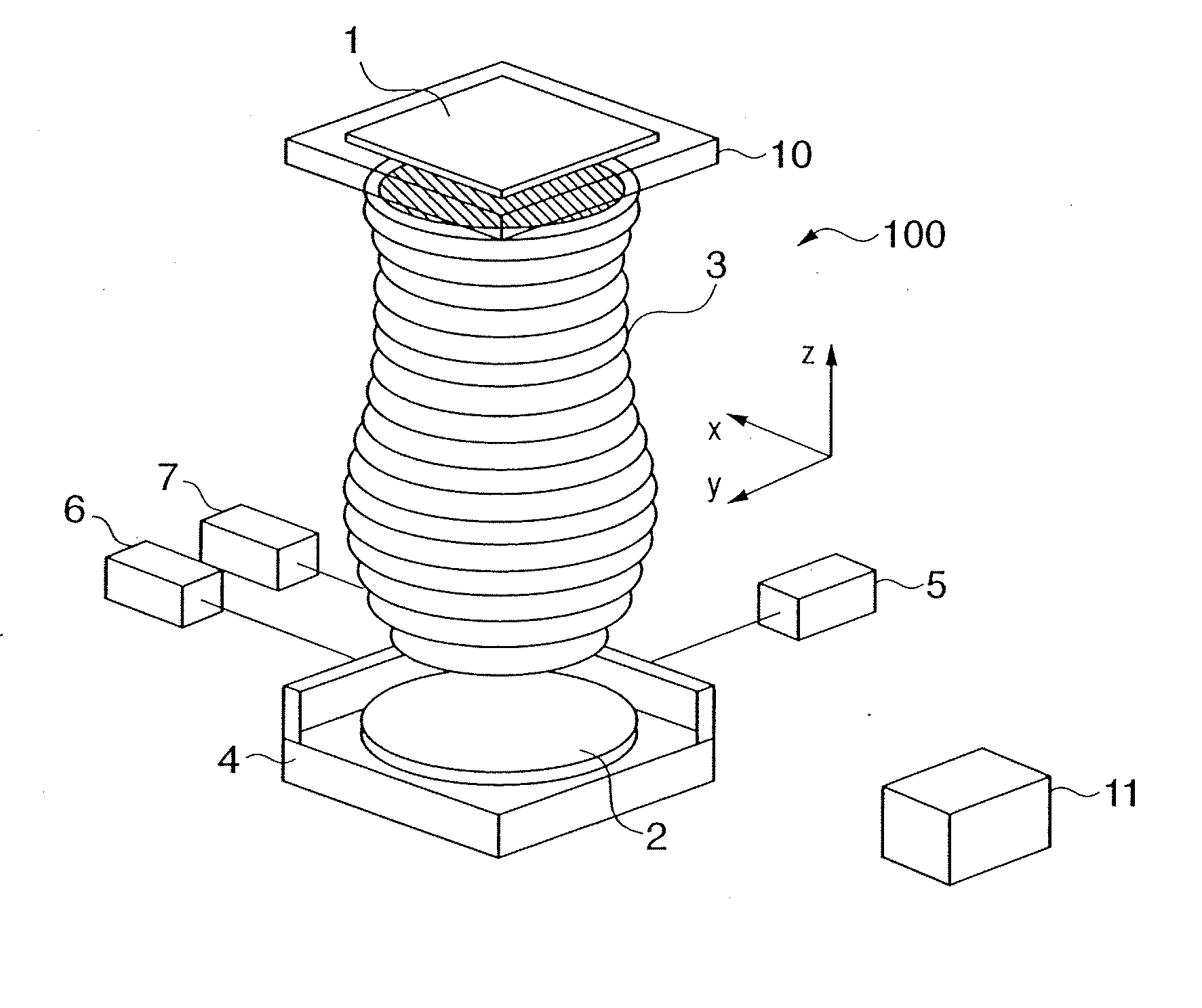
[0030]FIG. 3 is a flowchart for explaining automatic adjustment of a projection optical system 3 according to the Automatic adjustment is controlled by a control unit 11. A block 101 executes a process of measuring the wavefront aberration of the projection optical system 3. A block 102 expands the wavefront aberration by J Zernike orthogonal functions for image heights at H points to obtain Zernike coefficients Zjh.

[0031] A block 103 calculates aberration amounts from the optical design values of the projection optical system 3, and obtains main aberration amounts of N types (e.g., coma, curvature of field, astigmatism, distortion, and telecentricity) for evaluating the projection optical system 3 for image heights at H points. A block 104 accumulates pieces of information obtained by the blocks 101 to 103. As shown in FIG. 5, the aberration amount can be given as a wavelength value.

[0032] A block 105 divides the aberration amounts by an allowance and normalizes them in order to ...

second embodiment

[0067]FIG. 4 is a flowchart for explaining automatic adjustment of a projection optical system 3 according to the Automatic adjustment is controlled by a control unit 11. A block 101 executes a process of measuring the wavefront aberration of the projection optical system 3. A block 102 expands the wavefront aberration by J Zernike orthogonal functions for image heights at H points to obtain Zernike coefficients Zjh.

[0068] A block 103 calculates aberration amounts from the optical design values of the projection optical system 3, and obtains main aberration amounts of N types (e.g., coma, curvature of field, astigmatism, distortion, and telecentricity) for evaluating the projection optical system 3 for image heights at H points. A block 104 accumulates pieces of information obtained by the blocks 101 to 103.

[0069] A block 105 divides the aberration amounts by an allowance, normalizes them, and obtains normalized evaluation values (normalized aberration amounts) in order to optimiz...


PUM

PropertyMeasurementUnit
opticalaaaaaaaaaa
optical systemaaaaaaaaaa
weightsaaaaaaaaaa

Abstract

An optical apparatus including an image forming optical system having a movable optical element, and a driving mechanism which moves the optical element is disclosed. The apparatus comprises a first block which obtains a linear evaluation value by normalizing, by a first tolerance, an aberration expressed by a linear function of a position of the movable optical element out of aberrations of the optical system, and a quadratic evaluation value by normalizing, by a second tolerance, an aberration expressed by a quadratic function of the position out of the aberrations of the optical system, a second block which obtains a minimum value of a dummy variable by linear programming using an upper limit value of the linear evaluation value as the dummy variable, and a third block which determines a position of the optical element to be moved by the driving mechanism so as to minimize a weighted sum of the quadratic evaluation values with respect to a plurality of image heights by using, as the upper limit value of the linear evaluation value, a value prepared by adding a relaxation amount to the minimum value of the dummy variable that is obtained by the second block. The third block minimizes the weighted sum of the quadratic evaluation values by adjusting the weights assigned to the quadratic evaluation values and the relaxation amount.

Description

FIELD OF THE INVENTION [0001] The present invention relates to a technique for adjusting aberration of an optical system. BACKGROUND OF THE INVENTION [0002] As described in “T. Yoshihara et al., “Realization of very-small aberration projection lenses”, Proc. SPIE 2000, Vol. 4000-52” and Japanese Patent Laid-Open No. 11-176744, the projection optical system of a semiconductor exposure apparatus is prepared through the first step of measuring optical characteristics, the second step of calculating an adjustment amount for properly correcting various aberrations of the projection optical system on the basis of the measured optical characteristics, and the third step of actually adjusting or processing the projection optical system in accordance with the adjustment amount. [0003] Most of aberrations to be corrected change in proportion to the adjustment amount of each part. In order to minimize the maximum absolute value of each aberration, the adjustment amount of each part is determin...

Claims


Application Information

Patent Timeline
Patent Type & Authority Applications(United States)
IPC IPC(8): G01B9/00G02B7/00G02B27/00G03F7/20H01L21/027
CPCG03F7/70258G03F7/706G02B7/005G02B27/0068
Inventor FUKAGAWA, YOUZOUYOSHIHARA, TOSHIYUKINAKAMORI, MARIOSHINANO, YUJI
Owner CANON KK
Features
  • R&D
  • Intellectual Property
  • Life Sciences
  • Materials
  • Tech Scout
  • Unparalleled Data Quality
  • Higher Quality Content
  • 60% Fewer Hallucinations
Learn More