Image output apparatus

a technology of image output and output apparatus, which is applied in the direction of digital output to print units, instruments, digital computers, etc., can solve the problems of unsatisfactory extension of total processing time, and achieve the effect of simplifying hardware configuration, facilitating the design change of image output apparatus, and enhancing the versatility of respective image processing units

Inactive Publication Date: 2007-05-24
SEIKO EPSON CORP
View PDF19 Cites 23 Cited by
  • Summary
  • Abstract
  • Description
  • Claims
  • Application Information

AI Technical Summary

Benefits of technology

[0019] In the image output apparatus of this application, the second intermediate data different from the first intermediate data is transferred through the pass unit group, which is the different pathway from the image processing unit group executing the diverse series of image processing. Namely only the first intermediate data are transferred through the image processing unit group. This arrangement does not require significant change of the hardware configuration, for example, the bus width or the buffer capacity of each image processing unit, in response to a change in data structure or data volume of the second intermediate data. This enhances the versatility of the respective image processing units and facilitates the design change of the image output apparatus.
[0020] In the image output apparatus of this application, the second intermediate data used for the image processing by a certain image processing unit is transferable through the pass unit group to another image processing unit. The second intermediate data can then be reused for the image processing by the another image processing unit. This arrangement does not require individual generation of the same second intermediate data commonly used for image processing by multiple image processing units. This desirably simplifies the hardware configuration and reduces the manufacturing cost.
[0021] Each image processing unit may not use the second intermediate data generated by itself. For example, when the first image processing unit has the richer hardware resource than the second image processing unit, the first image processing unit may generate the second intermediate data, which is originally expected to be generated by the second image processing unit. The image output apparatus of this application enable flexible transmission of the second intermediate data through the pass unit group. Even when there is a difference between the hardware resources of the image processing units, this arrangement absorbs such a difference to facilitate the design of the image output apparatus.

Problems solved by technology

The high resolution of the input image, however, may cause undesirable extension of the total processing time by this proposed method, like the conventional methods.

Method used


Image

  • Image output apparatus
  • Image output apparatus
  • Image output apparatus

Examples


modified example 1

(H-1) MODIFIED EXAMPLE 1

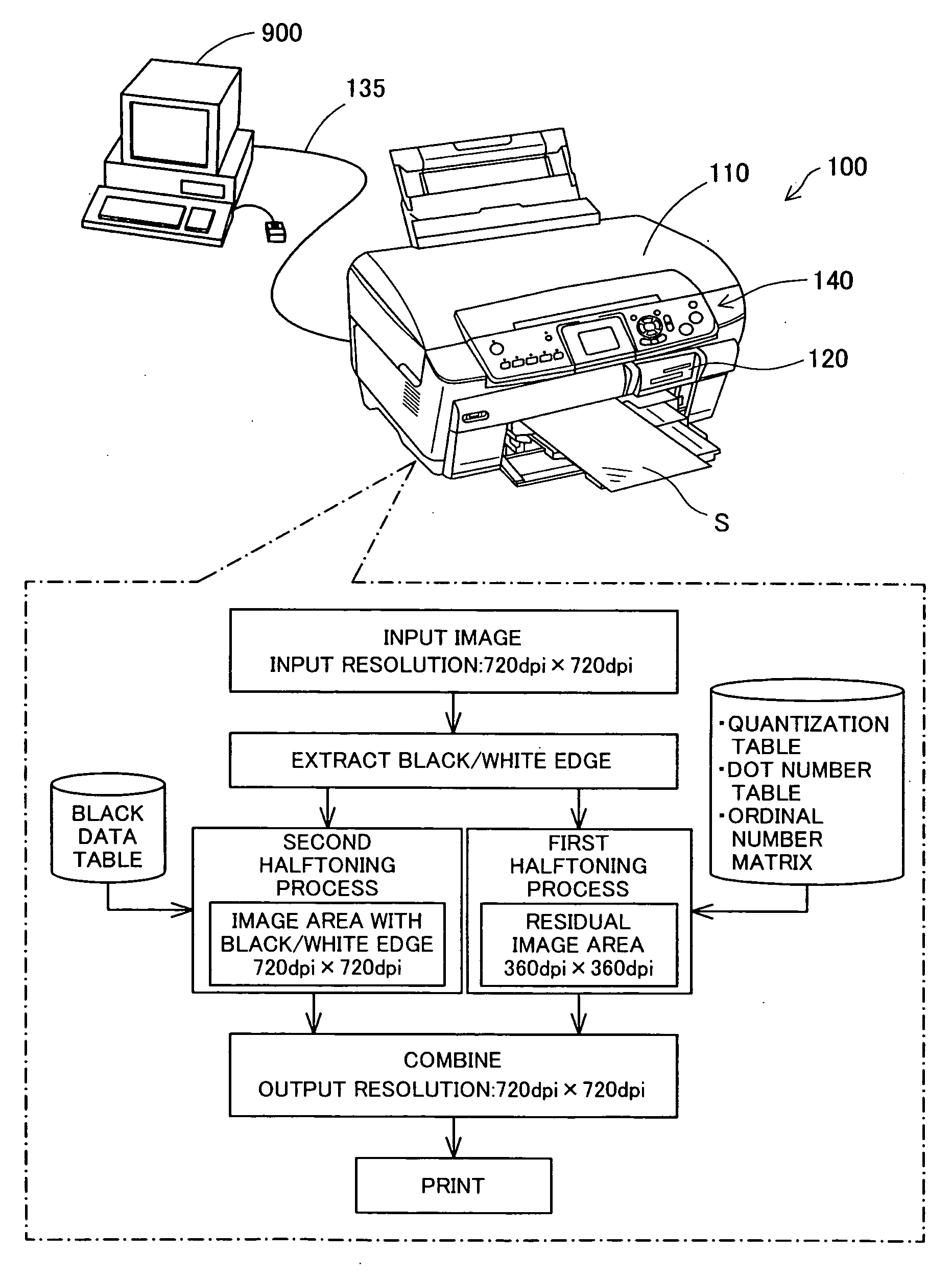
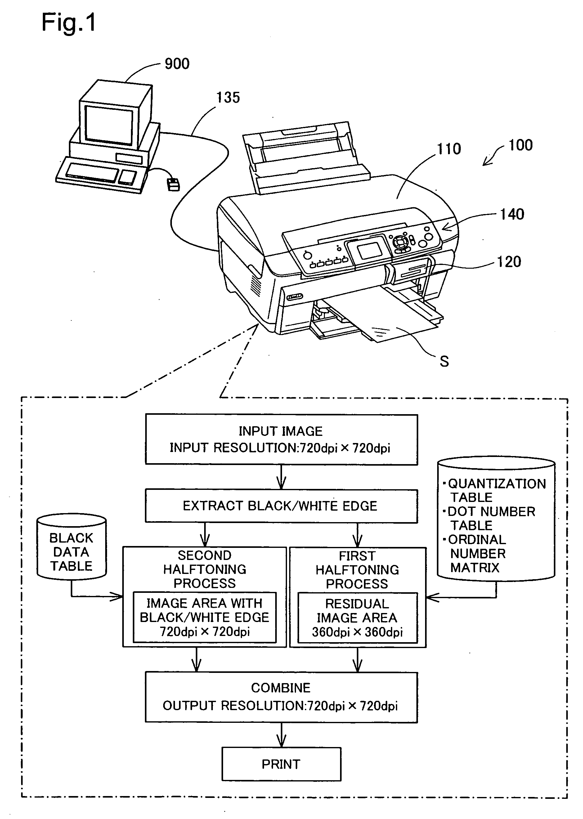
[0288] In the structure of the embodiment, the printing apparatus 100 alone performs the color conversion and encoding and decoding of the quantization data. In one modified structure, the devices located before the encoded data buffer EB, that is, the color conversion circuit 300, the encoder 410, and the data selector 420, may be incorporated in a different apparatus from the printing apparatus 100. The printing apparatus 100 and the different apparatus are interconnected by a predetermined communication path. A typical example of the different apparatus is the computer 900. In this modified structure, for example, a printer driver stored in the computer 900 executes the functions of the color conversion circuit 300, the encoder 410, and the data selector 420 by the software configuration. Such modification relieves the processing load of the printing apparatus 100. The quantization data encoded by the encoder 410 and the black / white edge data encoded by th...

modified example 2

(H-2) MODIFIED EXAMPLE 2

[0289] In the above embodiment, the ordinal number matrix has the size of 128×64. The ordinal number matrix is, however, not restricted to this size but may have a greater size (for example, 512×256). The ordinal number matrix of the greater size enables the efficient halftoning of input image data in larger size.

[0290]FIGS. 39 and 40 show examples of the 512×256 ordinal number matrix. The 512×256 ordinal number matrix of FIG. 39 is obtained by repeatedly allocating the 128×64 ordinal number matrix (hatched rectangle) of the embodiment with an offset of 64 pixels in the horizontal direction. The 512×256 ordinal number matrix of FIG. 40 is obtained by repeatedly allocating the 128×64 ordinal number matrix of the embodiment with an offset of 32 pixels in the vertical direction. The repeated application of the ordinal number matrix in the general size readily gives the ordinal number matrix in the greater size.

[0291] The ordinal number matrix in the greater si...

modified example 3

(H-3) MODIFIED EXAMPLE 3

[0292] The halftoning process of the embodiment keeps the high resolution with regard to the image part consisting of only black and white colors. The color combination for the high-resolution halftoning is not restricted to black and white but may be, for example, blue and white or green and white. The user may specify a desired color combination through the operation of the computer 900 or the operation panel 140. This arrangement enables characters and symbols expressed by any desired color other than black to be printed at the high resolution. When the user specifies a desired color for the characters and symbols, the black data table BT is replaced by the user's specified color data table. The user's specified color data table is readily creatable according to the black data table creation process described previously.


PUM


Abstract

The image output apparatus of the invention includes a main unit group of multiple main units connected in series to perform preset series of image processing and a pass unit group of multiple pass units connected in series to be parallel with the multiple main units. The averaged data of the tone values of four pixels generated by a black/white edge processing unit are sequentially transferred through the main unit group. The standard edge data and the noise data generated by a color conversion unit are sequentially transferred through the pass unit group, synchronously with the transfer of the averaged data through the main unit group. The data transferred through the pass unit group enters an inner-block smoothing unit to go through the smoothing process. The image output apparatus of the invention has the hardware configuration that allows flexible design change according to the required series of image processing.

Description

CLAIM OF PRIORITY [0001] The present application claims priority from Japanese Patent Applications P2005-270118A filed on Sep. 16, 2005 and P2005-270130A filed on Sep. 16, 2005, the contents of which are hereby incorporated by reference into this application. BACKGROUND OF THE INVENTION [0002] 1. Field of the Invention [0003] The present invention relates to an image output apparatus that inputs image data of a multi-tone image at a preset input resolution, converts the input image data to generate dot creation data, and creates dots according to the generated dot creation data on a printing medium at an output resolution of not lower than the preset input resolution. [0004] 2. Description of the Related Art [0005] The printing resolution of printers and other printing apparatuses has been increasing year after year and often exceeds the resolution of images taken with digital cameras. In such cases, one pixel of image data to be printed corresponds to a set of multiple pixels as pr...

Claims


Application Information

Patent Timeline
Patent Type & Authority Applications(United States)
IPC IPC(8): G06F3/12
CPCH04N1/4057
Inventor YADA, JUNYA
Owner SEIKO EPSON CORP
Why Eureka
Try Eureka