Prismatic battery

a battery and prismatic technology, applied in the field of prismatic batteries, can solve the problems of large heat generated by the contacting resistance between the battery's substrate and current collecting body, difficult to disconnect the weld, and easy to be disconnected, so as to reduce the possibility of internal short circuit

Active Publication Date: 2007-05-24
SANYO ELECTRIC CO LTD
View PDF2 Cites 111 Cited by
  • Summary
  • Abstract
  • Description
  • Claims
  • Application Information

AI Technical Summary

Benefits of technology

[0017] In consideration of the problems in the related art stated above, the present invention provides a prismatic battery with features of reducing a possibility of internal short-circuit caused by sputtered fine particles infiltrating an electrode while welding exposed substrates of an electrode to a pressing plate or a current collecting body using a high energy beam such as laser beam, and to be able to firmly weld the exposed substrates to the pressure plate or the current collecting body, even if the length of the exposed substrates of the electrode is short.

Problems solved by technology

However, when high-output discharge is performed, large current flows in the battery, and as a result, the heat generated by the contacting resistance between the battery's substrate and current collecting body becomes large.
Further, an excessive force will not be applied onto the welded tip of these substrates, as the substrates at the upper end of the negative electrode 51 are firmly pinched to the pinching section 54 as above, making it difficult for the weld to disconnect.
As the upper end is only laser welded in a state that the substrates 44 are bundled and pinched in the slit 41 of the negative electrode current collecting body 40, thereby causing problems such as the laser welding becoming incomplete and easily disconnected.
Accordingly, when subjected to vibration and impact, there is a possibility of some substrates coming loose.
But when such features are adopted, the space that the rolled electrode occupies within a battery package decreases, thereby causing a problem of reduced battery capacity.

Method used


Image

  • Prismatic battery
  • Prismatic battery
  • Prismatic battery

Examples


first embodiment

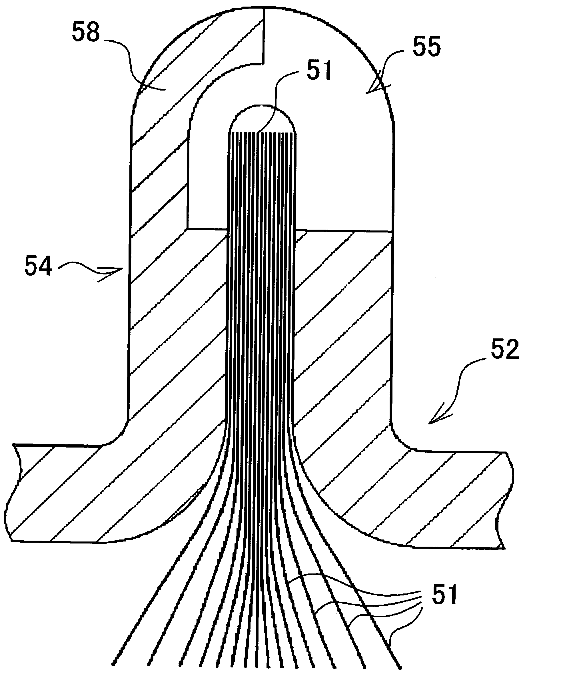
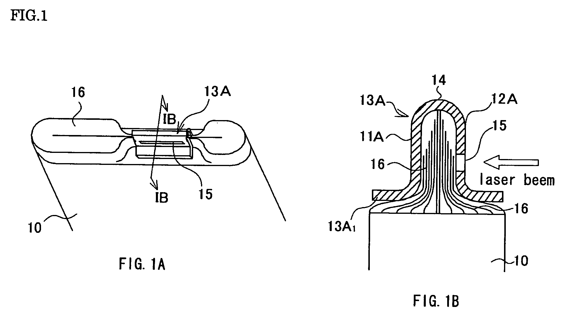
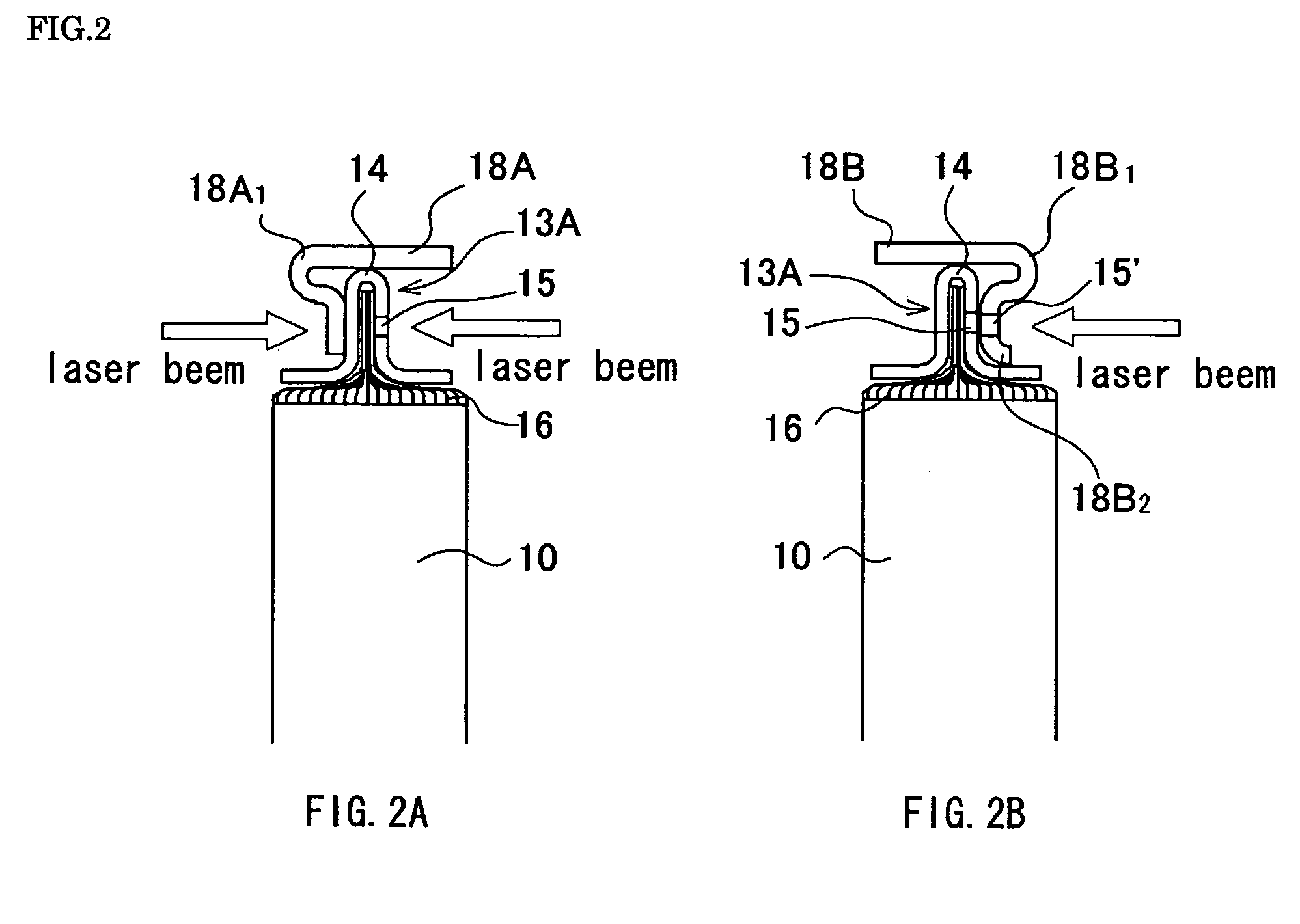
[0064] A prismatic battery of the first embodiment will be described with reference to FIGS. 1A through 3. FIG. 1A is a perspective view of a state wherein a pressing plate is mounted to a rolled electrode group in a flat form, and FIG. 1B is a cross-sectional view of FIG. 1A taken along a line IB-IB. FIG. 2A is a state wherein a current collecting body not having a further slit is mounted on the pressing plate mounted to the electrode group in a flat form of FIG. 1A, and FIG. 2B are also a state wherein a current collecting body having a slit is mounted, and are cross-sectional view corresponding to the cross-sectional view of FIG. 1A taken along a line IB-IB, respectively. FIG. 3 is a partial cross-sectional view of a prismatic battery of the first embodiment wherein an electrode group in a flat form is mounted with the current collecting body having a slit shown in FIG. 2B incorporated into a battery package.

[0065] The electrode group 10 in a flat form of the prismatic battery a...

second embodiment

[0074] If the rolled electrode group 10 in a flat form becomes thicker, the number of the exposed sections 16 of the positive electrode substrates or the negative electrode substrates inserted into a gap of the pressing plate 13A increases in the features of the pressing plate 13A as shown in the first embodiment, giving rise to the possibility that not all of the exposed sections 16 will fit into the gap of the pressing plate 13A unless an exposed margin is enlarged. Therefore, the features of a prismatic battery mounting a current collecting body to a thick rolled electrode group in a flat form are described as the second embodiment, with reference to FIGS. 4A and 4B. FIG. 4A is a perspective view in a state wherein a current collecting body is mounted to a rolled electrode group in a flat form of a prismatic battery of the second embodiment, and FIG. 4B is a cross-sectional view of FIG. 4A taken along a line IVB-IVB. In FIGS. 4A and 4B, the same reference numerals are given to de...

third embodiment

[0078] A prismatic battery of the third embodiment applies to a thick rolled electrode group 10 in a flat form, as in the case of the second embodiment, but which integrally combines s similar features to the pressing plate 13A of the prismatic battery in the first embodiment that was used as a pressing plate. Features of a current collecting body mounted to a rolled electrode group in a flat form of a prismatic battery in the third embodiment shall be described with reference to FIG. 5. FIG. 5 is a cross-section showing a state wherein a current collecting body is mounted to a rolled electrode group in a flat form of a prismatic battery in the third embodiment, and corresponding to the cross-sectional view of FIG. 4A taken along a line IVB-IVB. The same reference numerals are given and described to the same component parts of the current collecting body 18C of the prismatic battery in the second embodiment.

[0079] The electrode group 10 in a flat form of the prismatic battery in th...


PUM

PropertyMeasurementUnit
thicknessaaaaaaaaaa
thicknessaaaaaaaaaa
thicknessaaaaaaaaaa

Abstract

A prismatic battery according to one embodiment of the present invention includes a flat electrode group 10 stacked or rolled by mutually positive and negative electrodes with a separator therebetween, a pressing plate 13A, a current collecting body 18A or 18B and a plurality of exposed sections 16, at least one end of the positive and negative electrodes substrates in a width direction being uncoated with a positive or negative electrode mixture. The pressing plate 13A is welded to the exposed sections 16. The pressing plate 13A includes opposing surfaces with a space therebetween provided by folding back a metal plate, and includes a slit 15 along a folded back section at least to one of the opposing surface's side. The exposed sections 16 are inserted into a gap of the pressing plate 13A, and the exposed sections 16 and the pressing plate 13A are welded by a high energy beam from a transverse direction through the slit 15. This provides a prismatic battery for large current application in electric vehicles and hybrid electric vehicles.

Description

FIELD OF THE INVENTION [0001] The present invention relates to a prismatic battery having a rolled electrode composed of strips of positive and negative electrodes rolled with a strip separator interposed therebetween. More particularly, the present invention relates to a prismatic battery used for large current applications in electric vehicles, hybrid electric vehicles and the like. BACKGROUND OF THE INVENTION [0002] Against a background of intensifying movements for environmental protection, regulations on emissions of carbon dioxide and similar gases have been tightened. In the automobile world, development of electric vehicles (EVs) and hybrid electric vehicles (HEVs) is being vigorously pursued in addition to vehicles using gasoline, diesel oil, natural gas and other fossil fuels. Furthermore, the soaring rise in the price of fossil fuels over recent years has given a boost to the development of EVs and HEVs. [0003] For such EVs and HEVs, nickel-hydrogen secondary batteries an...

Claims


Application Information

Patent Timeline
Patent Type & Authority Applications(United States)
IPC IPC(8): H01M2/24H01M2/00H01M50/528H01M10/04H01M50/529H01M10/05H01M10/0585H01M10/0587H01M50/538H01M50/54H01M50/55H01M50/553H01M50/562
CPCH01M2/263H01M2/266H01M2/30H01M10/0525H01M10/345Y02E60/122Y02T10/7011Y02E60/10H01M50/538H01M50/54Y02P70/50H01M50/55H01M50/553H01M50/562H01M50/528H01M50/50Y02T10/70
Inventor YAMAUCHI, YASUHIRONANSAKA, KENJINAKANISHI, NAOYANOHMA, TOSHIYUKI
Owner SANYO ELECTRIC CO LTD
Why Eureka
Try Eureka