Cartridge element for dust collector

a technology of cartridge elements and dust collectors, which is applied in the directions of transportation and packaging, separation processes, filtration separation, etc., can solve the problems of low space utilization rate of cartridge elements, affecting the fixing effect, and the method may not tightly seal the flang

Inactive Publication Date: 2007-05-31
SINTOKOGIO LTD
View PDF19 Cites 10 Cited by
  • Summary
  • Abstract
  • Description
  • Claims
  • Application Information

AI Technical Summary

Benefits of technology

[0032] Since the dust collector of the invention has plate-type cartridge elements, each of which comprises a filter that is composed of two sheets of pleated filter medium being opposed to, and spaced apart from, each other, one end of the filter being closed and the other end of it being open, the cartridge elements being installed in the dust collector so that the successive edges that are shaped like ridges of the pleated filter medium appear to be vertical stripes, wherein the dust collector comprises filtering chambers that are stacked and communicate with each other and communicate with the entry of air with dust, a duct that communicates with

Problems solved by technology

However, the cylindrical cartridge elements made many open spaces when they were installed in a dust collector, and so it was a problem in that the rate of the use of the space by the cartridge elements was low.
S58-132524 has a problem in that the method may not tightly seal the flange if the pitch of the bolting is great.
Accordingly, the method has a problem in that the work for fixing takes a long time, and the cost of manufacturing the dust collector is also high.
Even when bolts are not used for fixing the flange, so as to ensure a sufficient airtightness, it has a problem in that the cost of manufacturing is great because a flange with a complicated shape may be needed, or an external force (e.g., an air cylinder, an electric motor, etc.) may need to be used.
However, the dust collector that uses the cylindrical cartridge element disclosed in Japanese Patent Laid-open Publication No. 2001-300237 has a problem in that when the elements are installed in the dust collector, since the elements are cylindrical, there exist many spaces between these elements, and so the rate of the use of the space by

Method used


Image

  • Cartridge element for dust collector
  • Cartridge element for dust collector
  • Cartridge element for dust collector

Examples


first embodiment

A. the Invention

[0062] Now we discuss the embodiment of the plate-type cartridge element of the invention.

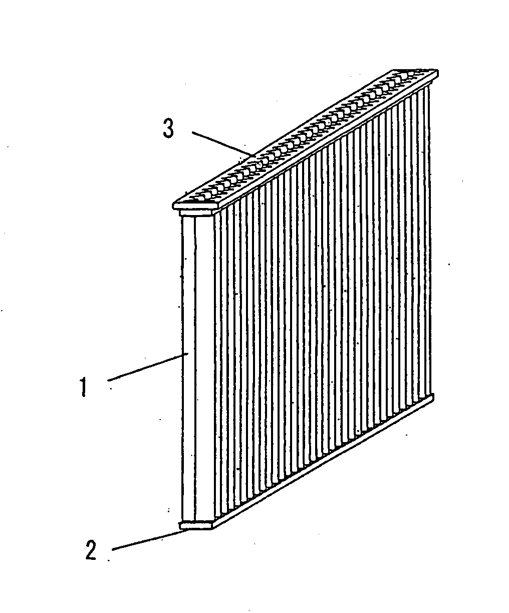
[0063] The first embodiment can achieve the function discussed above by making a cartridge element into a plate-type element, as follows.

[0064] First, the space for the elements in a dust collector can be utilized effectively and the rate of the use of the space by the element can be increased by making the cartridge element into a plate-type element.

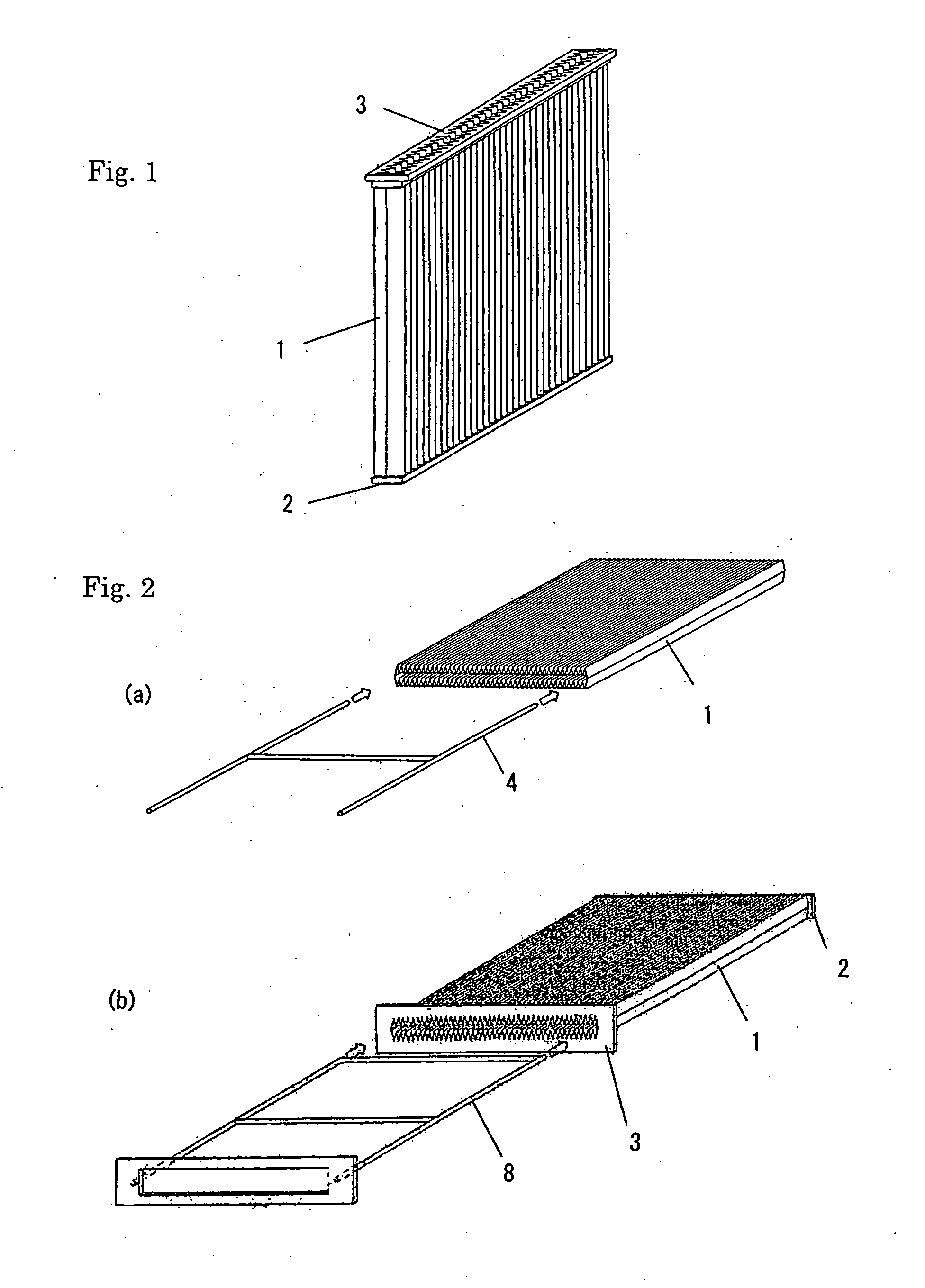
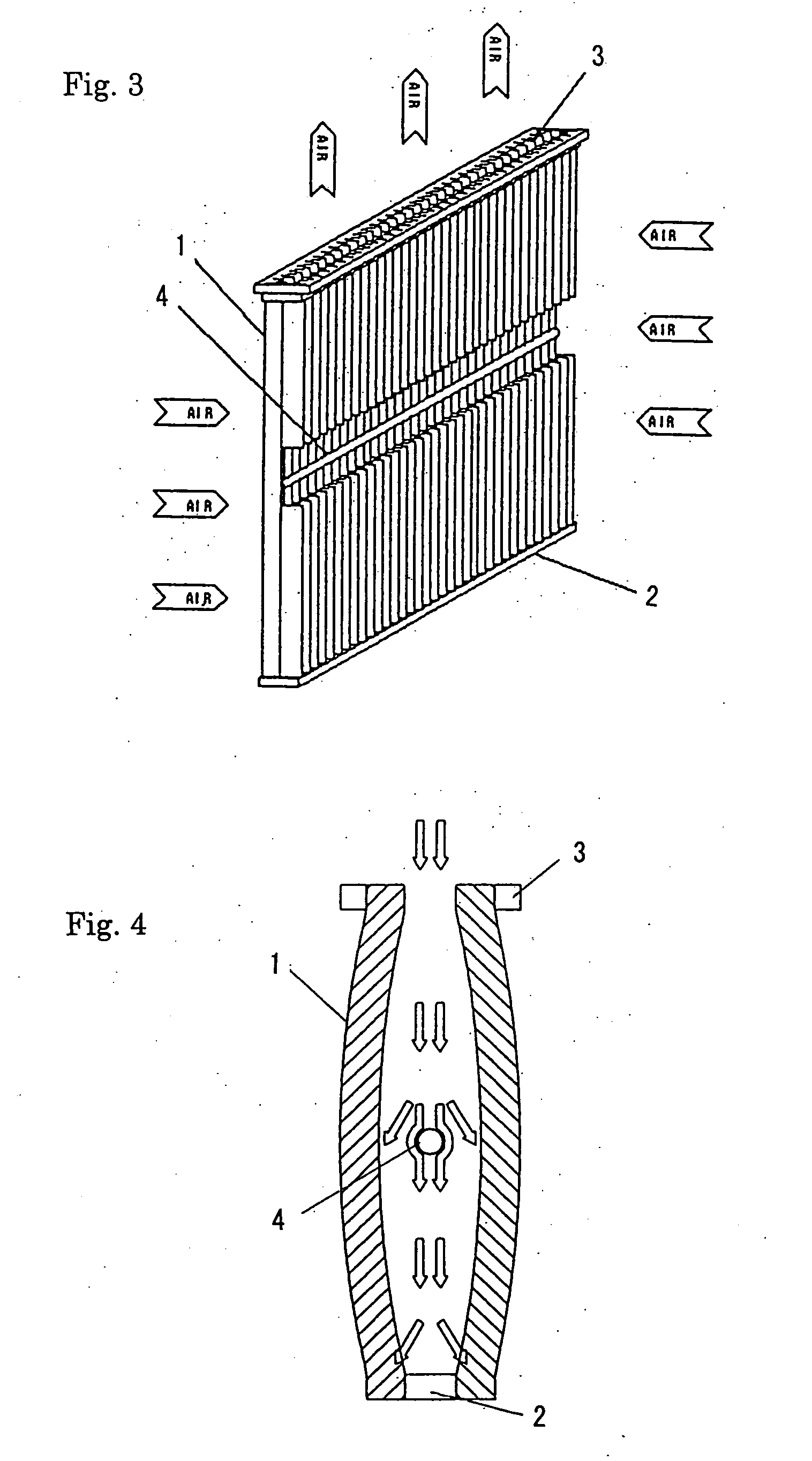
[0065] The plate-type-cartridge element of this embodiment is one that substantially has the shape of a plane plate when it is installed in a dust collector. The sectional view of it is rectangular. The ratio of the long and short sides of the rectangle is 1:0.08-1:0.15.

[0066]“Pleated” of this embodiment denotes being made with a configuration that has cross section in the shape of successive Vs. Any angles of the gradients of the two sides of every V-shape are acceptable. Both of them may be at the same angle or one of them may...

second embodiment

B. the Invention

[0079] Now, we discuss the second embodiment of the invention in detail. The embodiment uses a plate-type cartridge element 15 as a cartridge element based on drawings. As shown in FIG. 7, at the bottom of a duct 11 that is installed in a predetermined position in a dust collector, guiding members 12 are fixed at intervals and have more than one inclined elliptic hole 12a. Inside each guiding member 12, a drilled rail 13 that has connecting holes 13a that correspond to the inclined elliptic holes 12a is attached (see FIG. 9).

[0080] The guiding members 12 and the rails 13 are coupled by the coupling devices 14 that are inserted through the inclined elliptic holes 12a and the connecting holes 13a. The rails 13 have a sliding member 16, which has more than one opening 16a to be inserted in the plate-type cartridge elements 15. More than one (in this embodiment, three) plate-type cartridge elements 15 are inserted in the openings that are made on the sliding member 16. ...

third embodiment

C. the Invention

[0095] Now, we discuss the third embodiment of the invention in detail based on the drawings. In reference to FIG. 12, on the upper part of each of the filtering chambers that are stacked and form a number of rows (three rows in this embodiment) and that communicate with each other, a number of ducts 32 are installed. They are spaced apart from each other (see FIG. 14). In each filtering chamber 31, the plate-type cartridge elements are installed and each of them is attached under the duct 32 and is detachable.

[0096] Now, we discuss the plate-type cartridge element 33. In this embodiment, “plate-type” means substantially having the shape of a plane plate as a whole, and a “plate-type cartridge element” means a plate-type filter unit that can be easily attached and detached. In reference to FIG. 15, we specifically discuss the plate-type cartridge element 33 of this embodiment as follows. A filter 33b, which is composed of two sheets of pleated filter medium 33a and ...


PUM

PropertyMeasurementUnit
Sizeaaaaaaaaaa
Shapeaaaaaaaaaa
Stiffnessaaaaaaaaaa

Abstract

A cartridge element and a dust collector is provided that can achieve a decrease in the size of a dust collector using a cartridge element, can effectively disperse dust, can be easily used, and has a simple structure.
The cartridge element is a plate-type element and comprises a planate filter 1 composed of a cylindrically-formed pleated filter medium, a cap 2 that maintains the pleats and the opening of it in a planate shape, an upper-end member 3, and a reinforcing material 4 that is made by pipes or a round bar that is made by resin.

Description

FIELD OF THE INVENTION [0001] The present invention relates to a cartridge element for a dust collector, a mechanism to attach and detach the cartridge element, and a dust collector using the cartridge element. DESCRIPTION OF THE PRIOR ART [0002] A cylindrical cartridge element used in a dust collector is in the public domain (e.g., see Japanese Patent Laid-open Publication No. 2001-269528, FIG. 1). However, the cylindrical cartridge elements made many open spaces when they were installed in a dust collector, and so it was a problem in that the rate of the use of the space by the cartridge elements was low. [0003] A conventional method for attaching cartridge elements to a dust collector is to provide a flange at one end of each cartridge element and to fix each flange by bolts to the dust collector with a packing (e.g., see Japanese Utility-Model Laid-open Publication No. S58-132524, FIG. 3). [0004] However, the method for attaching as described in Japanese Utility-Model Laid-open ...

Claims


Application Information

Patent Timeline
IPC IPC(8): B01D46/00B01D46/24B01D46/52
CPCB01D46/0005B01D46/0009B01D46/521B01D46/2411B01D46/4227B01D46/0068B01D46/71
Inventor IKENO, HIDENORIWATANABE, HIROAKIKITAHORA, KAZUHIKO
Owner SINTOKOGIO LTD
Why Eureka
Try Eureka