Engine and valvetrain with dual pushrod lifters and independent lash adjustment

a pushrod lifter and pushrod technology, applied in the direction of valve arrangements, machines/engines, mechanical equipment, etc., can solve the problems of high cost of sohc and dohc systems, and large package width relative to cam-in-block design, so as to reduce or eliminate noise, vibration and harshness, and eliminate wear mechanisms. , the effect of increasing the stress

Inactive Publication Date: 2007-05-31
FORD GLOBAL TECH LLC
View PDF30 Cites 18 Cited by
  • Summary
  • Abstract
  • Description
  • Claims
  • Application Information

AI Technical Summary

Benefits of technology

[0009] The present invention provides a number of advantages. For example, the present invention provides embodiments with a dedicated lash adjuster for each valve associated with a particular lifter to compensate for thermal, wear, and tolerance effects and to insure that the valve motion remains very close to the design intent throughout the life of the engine. A common lifter for tandem valve operation with independent lash adjusters according to the present invention should reduce or eliminate noise, vibration, and harshness associated with valve pairs failing to open or close together and / or having different or higher than intended seating velocities. The present invention provides coupled, synchronous motion for each valve pair and allows individual compensation for valve spring force differences, differences in valve / seat wear, and differences due to the rocker arm force not being applied at the mid-point between valve centerlines which is liable to occur using a valve bridge design, for example. In addition, the present invention eliminates wear mechanisms associated with bridged valvetrain implementations, such as pitching and rolling of the bridge resulting in increased stresses on the bridge / rocker arm interface resulting in undesirable contact between the bridge and valve stem tips. Use of single plane stamped steel rocker arms having a ball / socket pivot according to the present invention facilitate packaging while reducing moving mass and increasing valve gear natural frequency. The ball / socket pivot point can be placed so that one rocker arm is significantly longer than the other rocker arm of a valve pair, but the rocker ratios are substantially identical to provide substantially identical valve open, close, and peak lift points.

Problems solved by technology

This may result in one valve opening late and / or at valve closure, one valve may seat first causing the other valve to seat late with a higher than intended velocity.
In addition, valve stem tips are edge loaded by the bridge with higher stresses resulting in higher rates of wear and potential noise, vibration, and harshness (NVH) concerns.
While single overhead cam (SOHC) and dual overhead cam (DOHC) systems have independently controlled valves to address some of these issues, the SOHC and DOHC systems are significantly more expensive and have large package width relative to a cam-in-block design.

Method used


Image

  • Engine and valvetrain with dual pushrod lifters and independent lash adjustment
  • Engine and valvetrain with dual pushrod lifters and independent lash adjustment
  • Engine and valvetrain with dual pushrod lifters and independent lash adjustment

Examples


Embodiment Construction

)

[0016] As those of ordinary skill in the art will understand, various features of the present invention as illustrated and described with reference to any one of the Figures may be combined with features illustrated in one or more other Figures to produce embodiments of the present invention that are not explicitly illustrated or described. The combinations of features illustrated provide representative embodiments for typical applications. However, various combinations and modifications of the features consistent with the teachings of the present invention may be desired for particular applications or implementations.

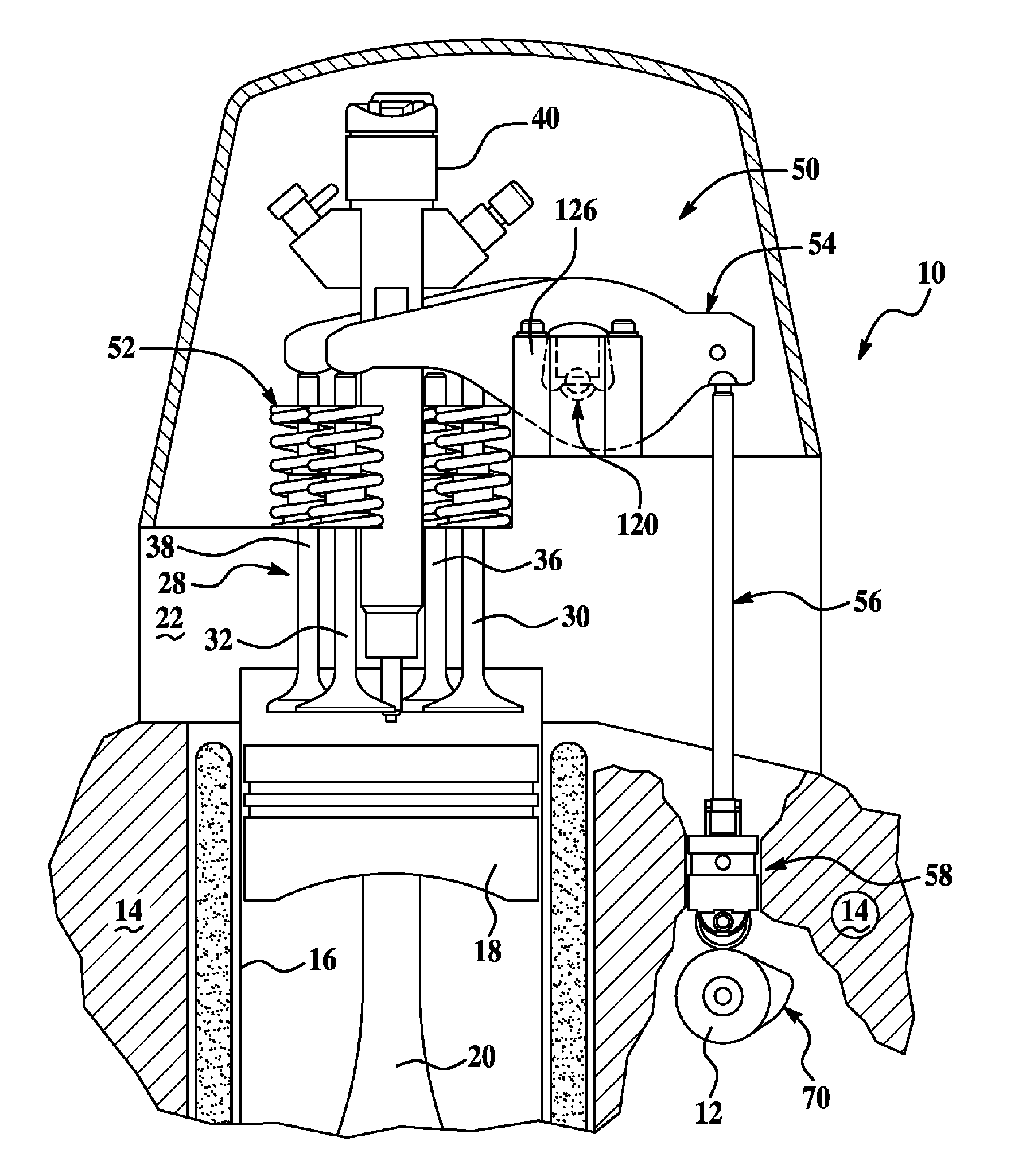
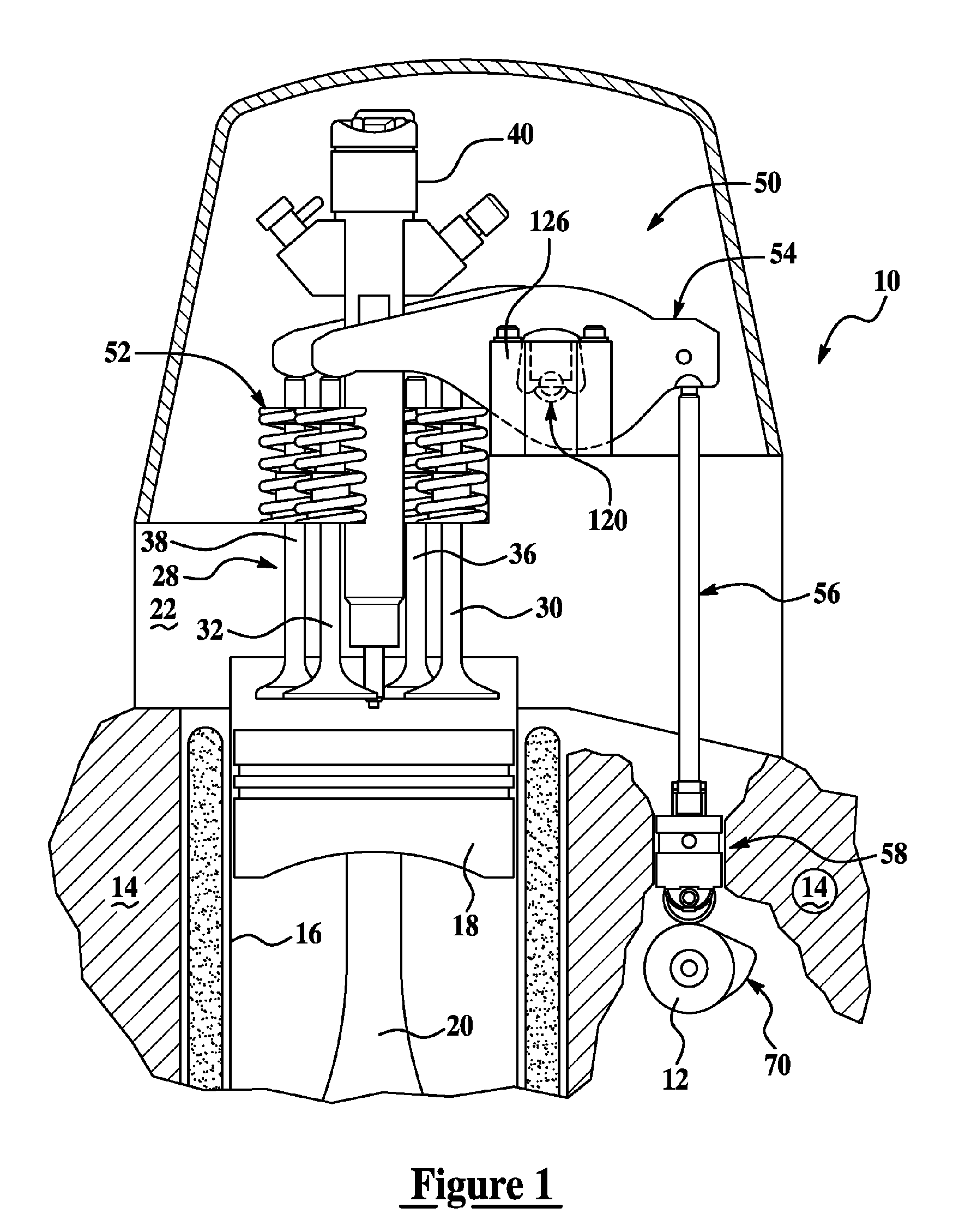
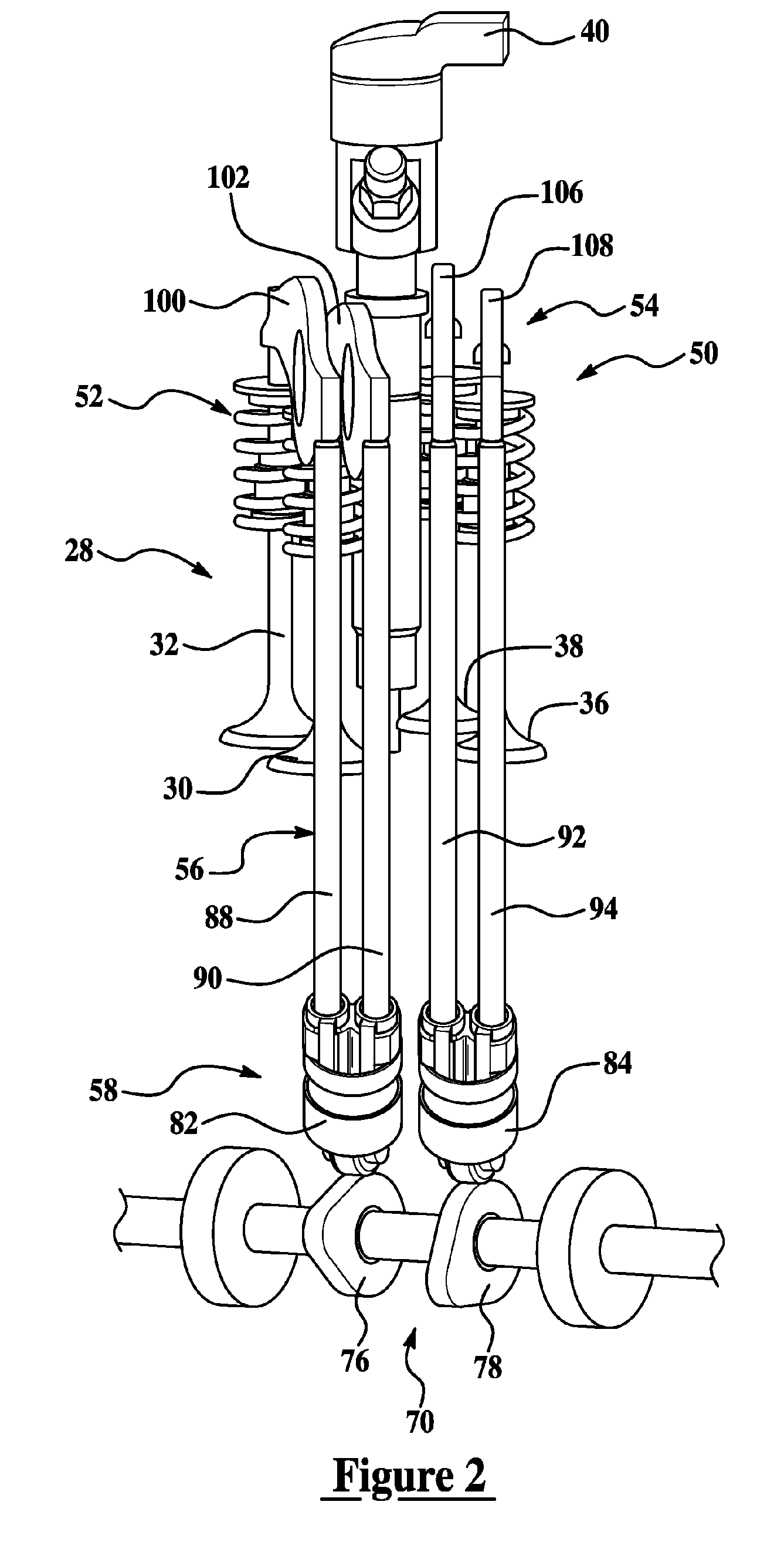
[0017]FIGS. 1-3 illustrate operation of an internal combustion engine and valvetrain according to a representative embodiment of the present invention. Multiple cylinder internal combustion engine 10 is generally of conventional design with the exception of various valvetrain components as described herein. As such, various conventional features associated with the e...


PUM


Abstract

A multiple cylinder internal combustion engine having a camshaft-driven valvetrain with a camshaft disposed within an engine block includes at least two intake and / or exhaust valves with a pair of valves operated by a common camshaft lobe and a cam follower. The valvetrain may include independently operable mechanical or hydraulic lash adjusters. The cam follower contacts the common camshaft lobe and at least two pushrods with each pushrod having an associated single plane rocker arm which couples to a fulcrum mounted to the cylinder head to actuate the at least two valves.

Description

BACKGROUND OF THE INVENTION [0001] 1. Field of the Invention. [0002] The present invention relates to multiple cylinder internal combustion engines having intake / exhaust valves operated by a camshaft positioned in an engine block with an associated valvetrain. [0003] 2. Background Art. [0004] Conventional internal combustion engines use a camshaft-driven valvetrain to operate intake and exhaust valves that control the exchange of gases in the combustion chambers formed between the engine block and cylinder head. Engines are often categorized by the location of the camshaft relative to the valves, with overhead cam valvetrains driven by a camshaft in the cylinder head over the valves, and pushrod valvetrains or “cam-in-block” valvetrains having the camshaft located in the engine block with the valves operated using pushrods and rocker arms. [0005] Current four-valve-per-cylinder pushrod engines include two intake valves and two exhaust valves for each cylinder. Each pair of valves is...

Claims


Application Information

Patent Timeline
Patent Type & Authority Applications(United States)
IPC IPC(8): F01L1/26F01L1/18F01L1/14
CPCF01L1/146F01L1/182F01L1/26F01L2001/2427F01L2101/00F01L2103/00F01L2105/00F01L2303/00F01L2301/00F01L2305/00
Inventor DIGGS, MATTHEWBEABER, WALLYINNES, ROBERT
Owner FORD GLOBAL TECH LLC
Why Eureka
Try Eureka