Harness routing structure for vehicle

a routing structure and vehicle technology, applied in the direction of electric propulsion mounting, coupling device connection, electric propulsion mounting, etc., can solve the problem of high voltage harness breakage, reduce the life prevent damage, and reduce the lifetime of high voltage harnesses without affecting driving performance

Inactive Publication Date: 2007-05-31
NISSAN MOTOR CO LTD +1
View PDF13 Cites 32 Cited by
  • Summary
  • Abstract
  • Description
  • Claims
  • Application Information

AI Technical Summary

Benefits of technology

[0005] (2) Since the engine intake duct exists on the detour path for routing the high voltage harness; a cross section of the engine intake duct needs to be reduced in order to route the high voltage harness under the situation where a space up to a vehicle body is limited. As a result, an output power of engine is reduced.
[0006] (3) Since the detour path for routing the high voltage harness also includes a high-temperature portion of engine exhaust system; the high voltage harness receives a heat deterioration due to high heat derived from the engine exhaust system. Accordingly, a durability life-time of the high voltage harness is shortened.
[0007] It is therefore an object of the present invention to provide a high voltage harness routing structure for a vehicle, devised to more certainly protect the high voltage harness covered by a protector from a cut or a damage at the time of collision, while preventing the damage and the lifetime reduction of high voltage harness without affecting a driving performance.

Problems solved by technology

However, in the above-described previously proposed high voltage harness routing structure for a hybrid vehicle, there are the following problems.
Hence, there is a possibility that the high voltage harness is broken.

Method used


Image

  • Harness routing structure for vehicle
  • Harness routing structure for vehicle
  • Harness routing structure for vehicle

Examples


first embodiment

[0040] A configuration of the harness routing structure in the first embodiment will now be explained.

[0041] [System Configuration of Hybrid Vehicle]

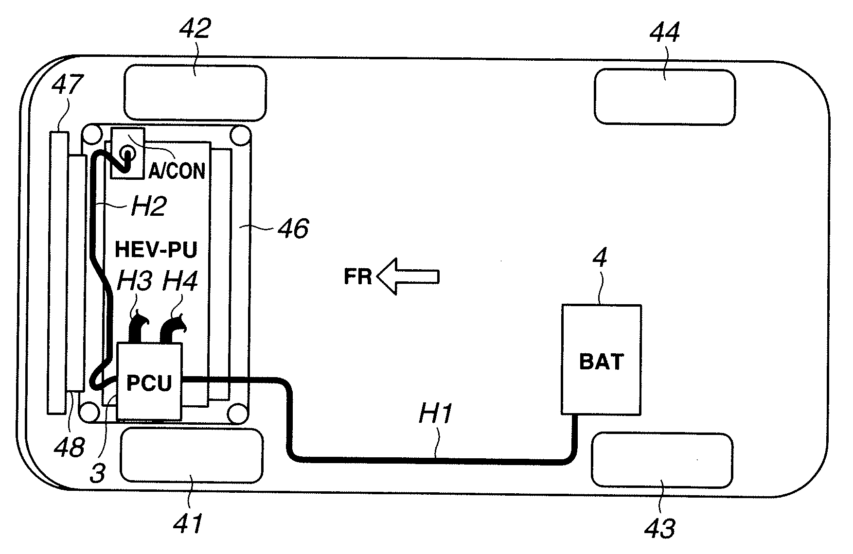
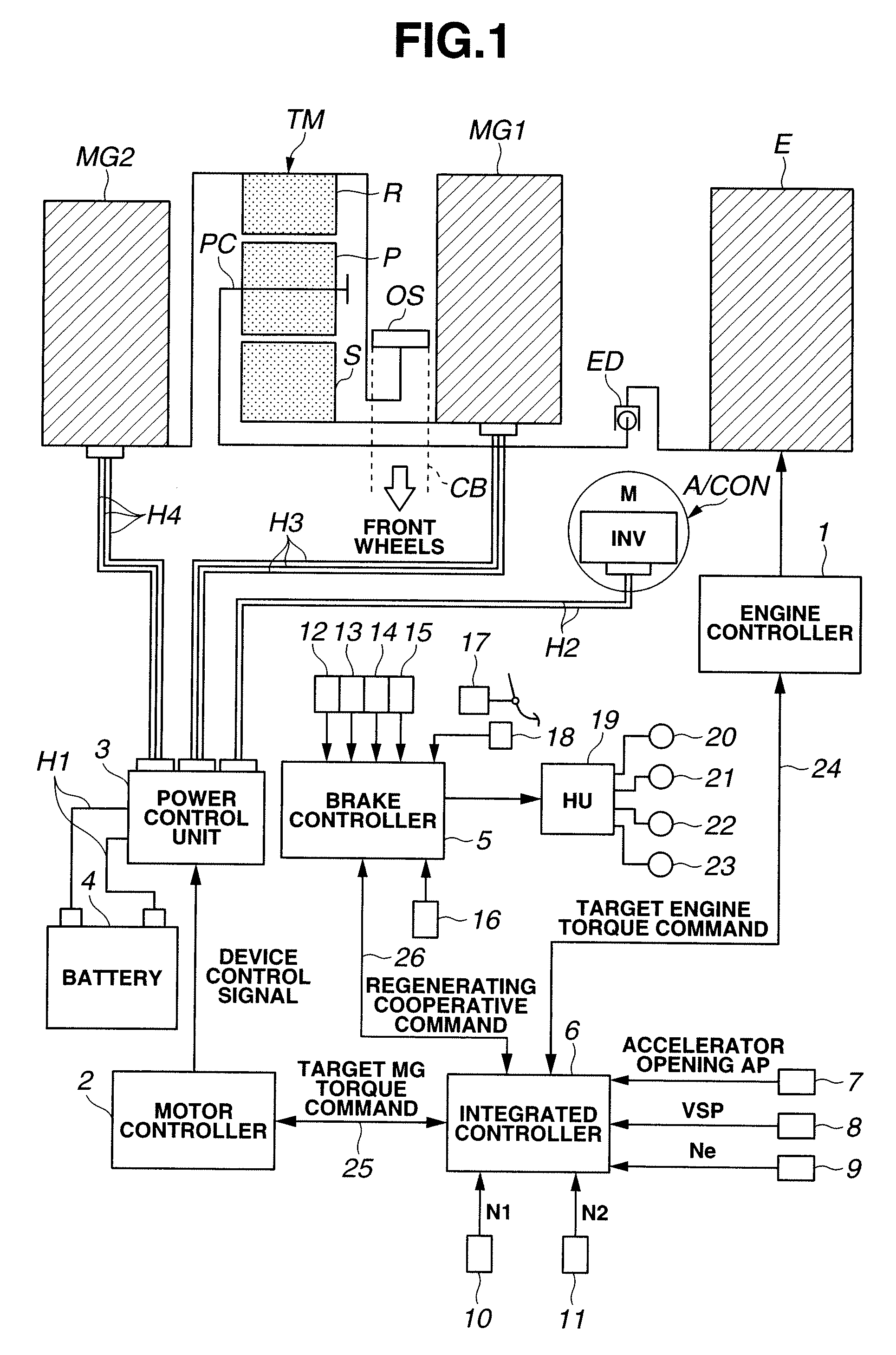
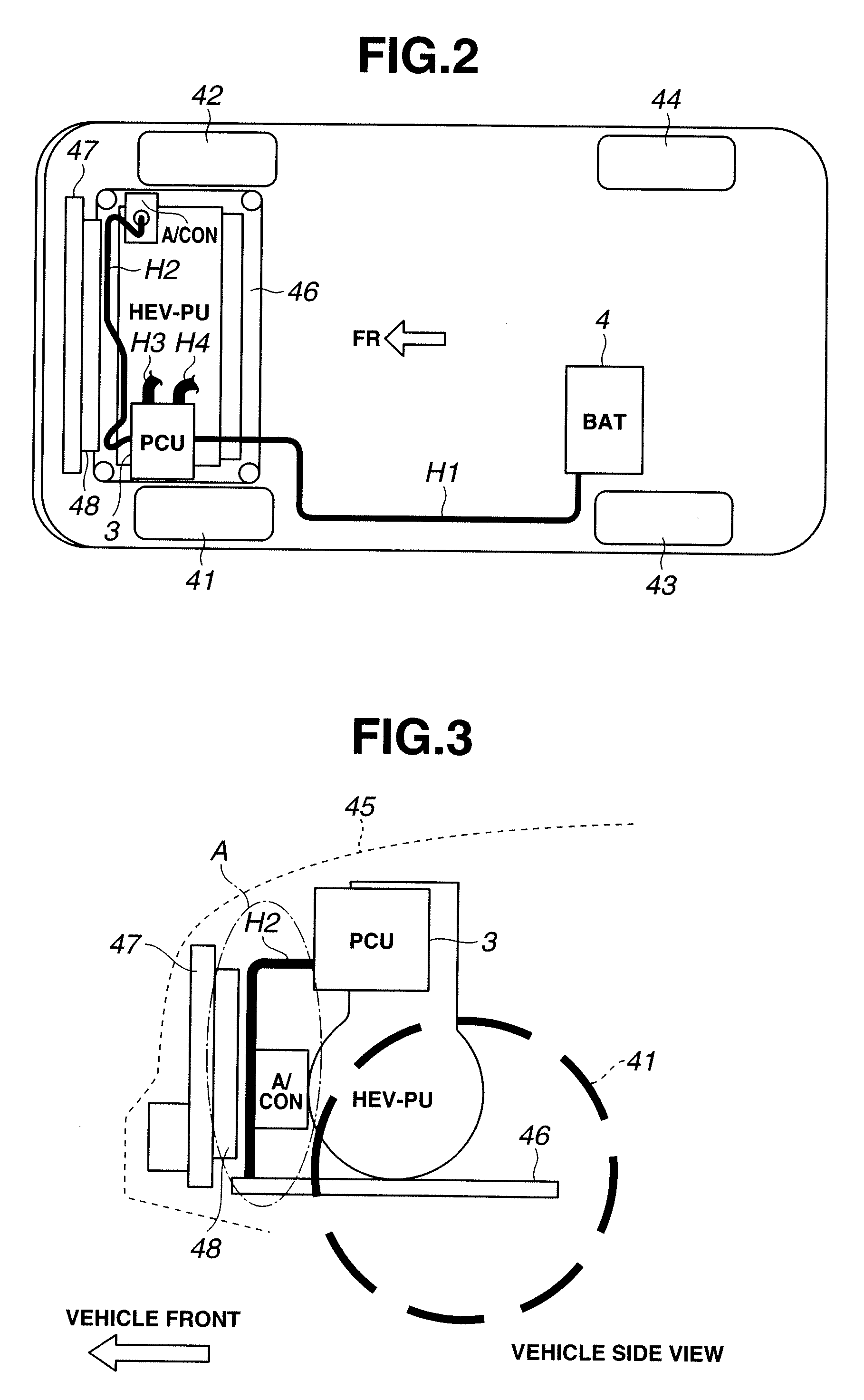
[0042]FIG. 1 is a schematic block diagram showing a drive system of a hybrid vehicle (as one example of vehicle) employing the harness routing structure of the first embodiment. As shown in FIG. 1, the drive system of hybrid vehicle in the first embodiment includes an engine E, a first motor / generator MG1, a second motor / generator MG2, an output sprocket OS, a power (torque) split mechanism TM, and an electrical compressor unit (electrical auxiliary unit) A / CON.

[0043] Engine E is a gasoline engine or diesel engine. Valve opening of a throttle valve of engine E or the like is adjusted according to a control command derived from an engine controller 1 described below.

[0044] Each of first motor / generator MG1 and second motor / generator MG2 is a synchronous-type motor / generator, in which a permanent magnet is set or buried in a rotor and ...


PUM


Abstract

A high-voltage harness routing structure includes: a subframe; a driving power unit; an electric power distribution unit; an electrical auxiliary unit arranged to cause the driving power unit to be sandwiched between the electric power distribution unit and the electrical auxiliary unit; and a high voltage harness connecting the electric power distribution unit with the electrical auxiliary unit in a routing path. In this routing path, the high voltage harness drops from the electric power distribution unit toward the subframe and then extends along the subframe in a vehicle-width direction. The high-voltage harness routing structure further includes a driving power unit mount including a mount main body arranged apart from the subframe to form a space between the mount main body and the subframe; and a protector that covers at least a high-voltage harness's portion extending along the subframe in the vehicle-width direction and interfering with the driving power unit mount. The high voltage harness covered by the protector is passed through the space.

Description

BACKGROUND OF THE INVENTION [0001] The present invention relates to a harness routing structure for a vehicle in which an electric-power distribution unit and an electrical auxiliary unit installed to sandwich a driving power unit are connected through a high voltage harness with each other. [0002] An internet website, TOYOTA home page>showroom>alphard hybrid>function mechanism>hybrid system (URL: http: / / toyota.jp / alphardhybrid / dynamism / hybrid / index.html) [web searching on Oct. 5, 2005] discloses a previously proposed high voltage harness routing structure for a hybrid vehicle in which a power control unit (inverter) arranged at an upper position of one end side of a hybrid power unit equipped with a transversely mounted engine and motor / generators, and an electric compressor arranged at a lower front position of another end side of the hybrid power unit to sandwich the hybrid power unit between the power control unit and the electric compressor are connected with each o...

Claims


Application Information

Patent Timeline
Patent Type & Authority Applications(United States)
IPC IPC(8): B60K1/00
CPCB60K6/445B60K6/48Y02T10/6221B60H1/3222Y02T10/6239Y02T10/62
Inventor YAJIMA, TSUTOMUOMORI, MOTOOSUGIYAMA, HIRONOBUYAMASHITA, KOJI
Owner NISSAN MOTOR CO LTD
Why Eureka
Try Eureka