Light-emitting device and organic electroluminescence light-emitting device

a light-emitting device and electroluminescence technology, applied in the field of light-emitting devices, can solve the problems of difficult to achieve the refractive index distribution and to completely prohibit the propagation, and achieve the effect of improving the light extraction efficiency of the light-emitting devi

Inactive Publication Date: 2007-05-31
ROHM CO LTD
View PDF9 Cites 54 Cited by
  • Summary
  • Abstract
  • Description
  • Claims
  • Application Information

AI Technical Summary

Benefits of technology

[0079] As explained above, according to this invention, the conversion from the waveguide mode to the radiation mode is made possible by use of the mode conversion means, thereby improving the light extraction efficiency of the light-emitting device such as an organic EL light-emitting device.

Problems solved by technology

Actually, however, it is difficult to achieve the refractive index distribution to totally prohibit the propagation, and therefore the propagation of a part of the waveguide mode 22 is suppressed from being converted to the radiation mode 23.

Method used


Image

  • Light-emitting device and organic electroluminescence light-emitting device
  • Light-emitting device and organic electroluminescence light-emitting device
  • Light-emitting device and organic electroluminescence light-emitting device

Examples


Embodiment Construction

[0161] An embodiment of the invention is explained below with reference to the accompanying drawings.

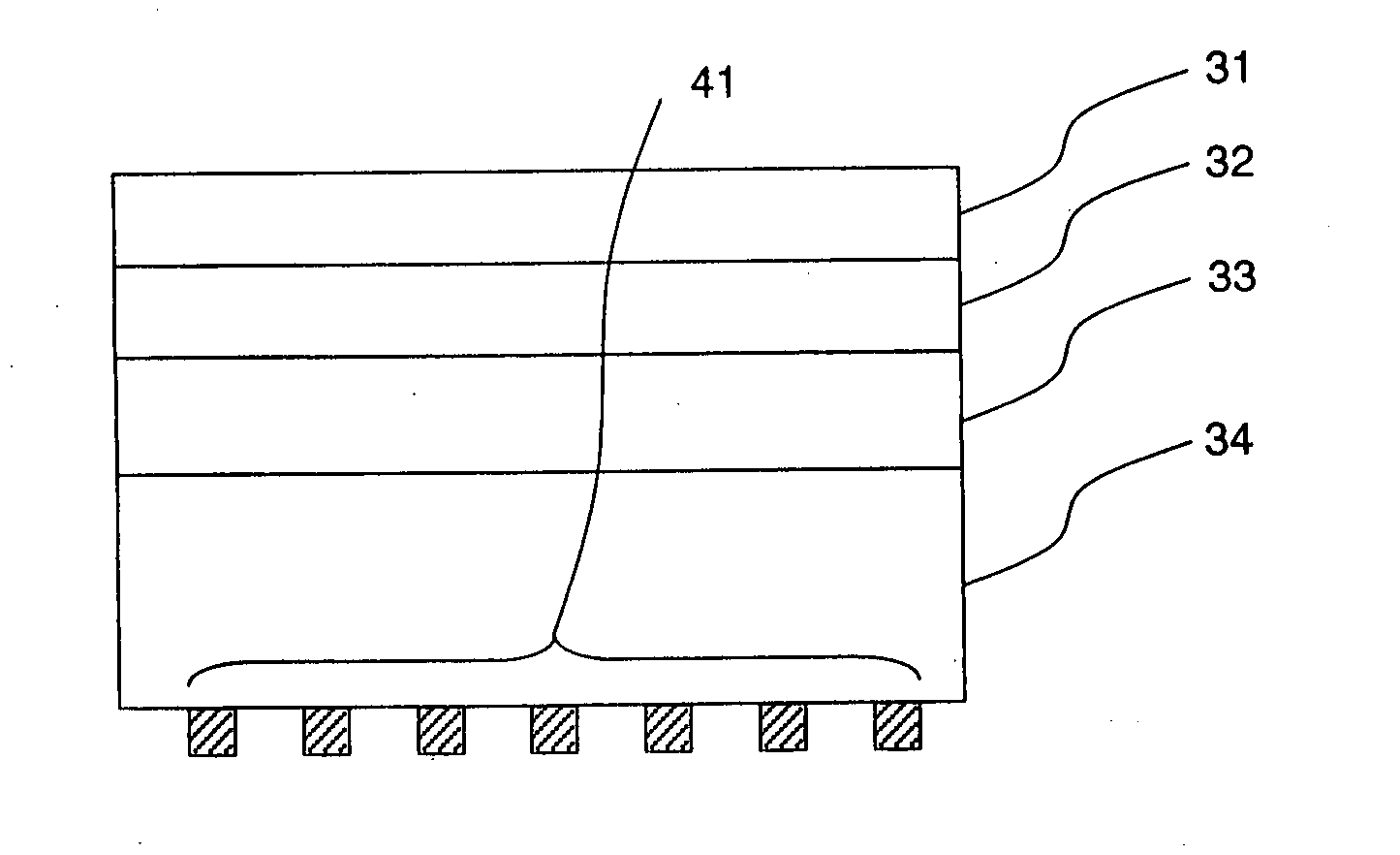
[0162] As a mode conversion means for converting the waveguide mode to the radiation mode, an example of the optical structure having a regularity of a refractive index distribution on the one-dimensional direction. In FIG. 4, numeral 22 denotes a waveguide mode, 23 a radiation mode, 25 an optical structure and 41 a mode conversion means. In FIG. 4, the optical structure 25 is arranged in the one-dimensional direction (horizontal direction in FIG. 4) as the mode conversion means 41. The refractive index of the optical structure 25 is set different from the refractive index of a material having no optical structure 25.

[0163] In the case where the optical structure 25 is arranged with such a period as to suppress the propagation of the light in the waveguide mode 22, the waveguide mode 22 is converted into the radiation mode 23 and radiated outside. The provision of this mode convers...


PUM

PropertyMeasurementUnit
refractive indexaaaaaaaaaa
light emission wavelengthaaaaaaaaaa

Abstract

In conventional organic EL light-emitting devices, the ITO used for a transparent electrode has a refractive index of about 2.0 larger than the refractive index of 1.5 of a transparent glass substrate. As a result, the mode of most of light traveling from the transparent electrode toward the glass substrate is the transparent electrode guided mode, and no light is emitted from the transparent electrode toward the glass substrate. According to the invention, the light extraction efficiency of conventional light-emitting devices such as organic EL light-emitting devices is improved by using mode conversion means so as to solve the problem that conventional light-emitting devices such as organic EL light-emitting devices have low light extraction efficiencies. A light-emitting device of the invention comprises a light-emitting layer on a substrate and mode conversion means for converting the mode from the guided mode into an emission mode. The mode conversion means is provided in the substrate, in the light-emitting layer, or at the interface between the substrate and the light-emitting layer.

Description

TECHNICAL FIELD [0001] This invention relates to a light-emitting device having a high light extraction efficiency, or in particular to an organic electroluminescence (hereinafter referred to as EL) light-emitting device having a high light extraction efficiency for the light emitted from an organic EL layer. BACKGROUND ART [0002] The organic EL light-emitting device is a highly promising self luminous element for use as a video display device such as a display and a surface light source. The organic EL light-emitting device is used for a video display device either as a part color system to emit a monochromatic light or as a full color system having areas to emit light in the three primary colors of red (R), green (G) and blue (B). The organic EL light-emitting device used as a surface light source is configured as a thin-film device. [0003] This organic EL light-emitting device is fabricated generally by laminating a transparent electrode constituting an anode, an organic EL layer...

Claims


Application Information

Patent Timeline
Patent Type & Authority Applications(United States)
IPC IPC(8): H01L33/00H01L51/00H01L51/30H01L51/52H05B33/02H05B33/14
CPCH01L51/0035H01L51/0036H01L51/0037H01L51/0038H01L51/0051H01L51/0052H01L51/0059H01L51/007H01L51/5262H01L51/5275H10K85/111H10K85/113H10K85/1135H10K85/114H10K85/611H10K85/615H10K85/631H10K85/6565H10K50/85H10K50/858H05B33/02H05B33/14
Inventor NODA, SUSUMUASANO, TAKASHIFUJITA, MASAYUKIOHATA, HIROSHI
Owner ROHM CO LTD
Why Eureka
Try Eureka