
Control signal transmitting and receiving techniques for video/audio processing IC and apparatus therefor

a control signal and video/audio processing technology, applied in the field of video players, can solve the problem of inefficient use of many pins for inputting control signals, and achieve the effects of reducing manufacturing costs, substantial flexibility, and easy modification of the design of the a/v i

Inactive Publication Date: 2007-05-31
SAMSUNG ELECTRONICS CO LTD
View PDF8 Cites 13 Cited by
  • Summary
  • Abstract
  • Description
  • Claims
  • Application Information

AI Technical Summary

Benefits of technology

[0008] To solve the above problems, it is an object of the present invention to provide improved control signal transmitting and receiving methods for efficiently transmitting and receiving control signals.
[0009] It is another object to provide an improved control signal transmitting and receiving apparatus for efficiently transmitting and receiving control signals.
[0010] It is also an object to provide a method and apparatus that reduces the number of pins and electrical lines leading to IC chips in a video player.
[0014] It is still yet another object to provide a method and an apparatus for a video player wherein when a circuit block requesting a control signal is added inside the A / V IC chip or the states to be controlled increases, there is no need to adjust pins in the A / V IC chip, and therefore, design of the A / V IC chip can be easily changed.
[0020] The present invention provides substantial flexibility in transmitting and receiving control signals. For example, even when a circuit block requesting a control signal is added inside the A / V IC, or the states to be controlled increases, there is no need to adjust pins in the A / V IC, and therefore, design of the A / V IC can be easily changed. Also, since the number of pins of the A / V IC decreases greatly compared to the conventional parallel transmitting and receiving method, the manufacturing cost of the A / V IC is reduced, and as the result, the competitiveness of products can be strengthened.

Problems solved by technology

Therefore, it is inefficient to have many pins for inputting control signals.

Method used


Image

  • Control signal transmitting and receiving techniques for video/audio processing IC and apparatus therefor
  • Control signal transmitting and receiving techniques for video/audio processing IC and apparatus therefor
  • Control signal transmitting and receiving techniques for video/audio processing IC and apparatus therefor

Examples


first embodiment

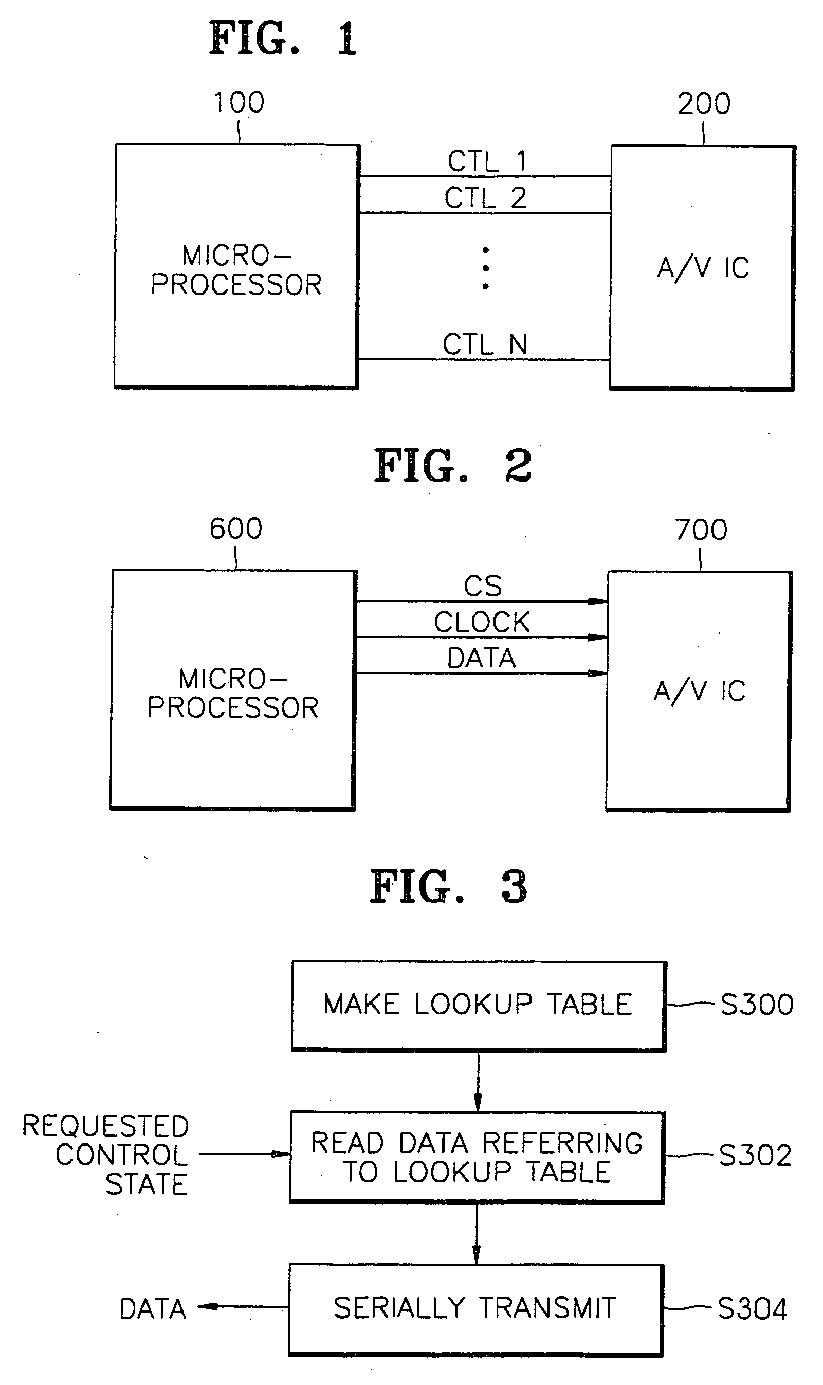
[0043]FIG. 5 is a block diagram for showing the structure of an apparatus according to the present invention. The apparatus shown in FIG. 5 corresponds to a case in which an A / V IC uses a serial transmission method and a microprocessor uses a parallel transmission method. The apparatus shown in FIG. 5 has a parallel / serial conversion apparatus (P / S converter) 500 separate from a microprocessor 100. The P / S converter 500 has a lookup table 502, and a shift register 504. The microprocessor 100 outputs control signals CTL1—CTLn determined according to a mode selected by a user and the state of an input A / V signal, etc. The lookup table 502 outputs mapped control signals shown in tables 1 through 3, using parallel control signals provided from the microprocessor 100 as address signals. The mapped (or encrypted) control signals output from the lookup table 502 are 1 to 3 bytes long, and stored in the shift register 504. The mapped control signals stored in the shift register 504 are sync...

second embodiment

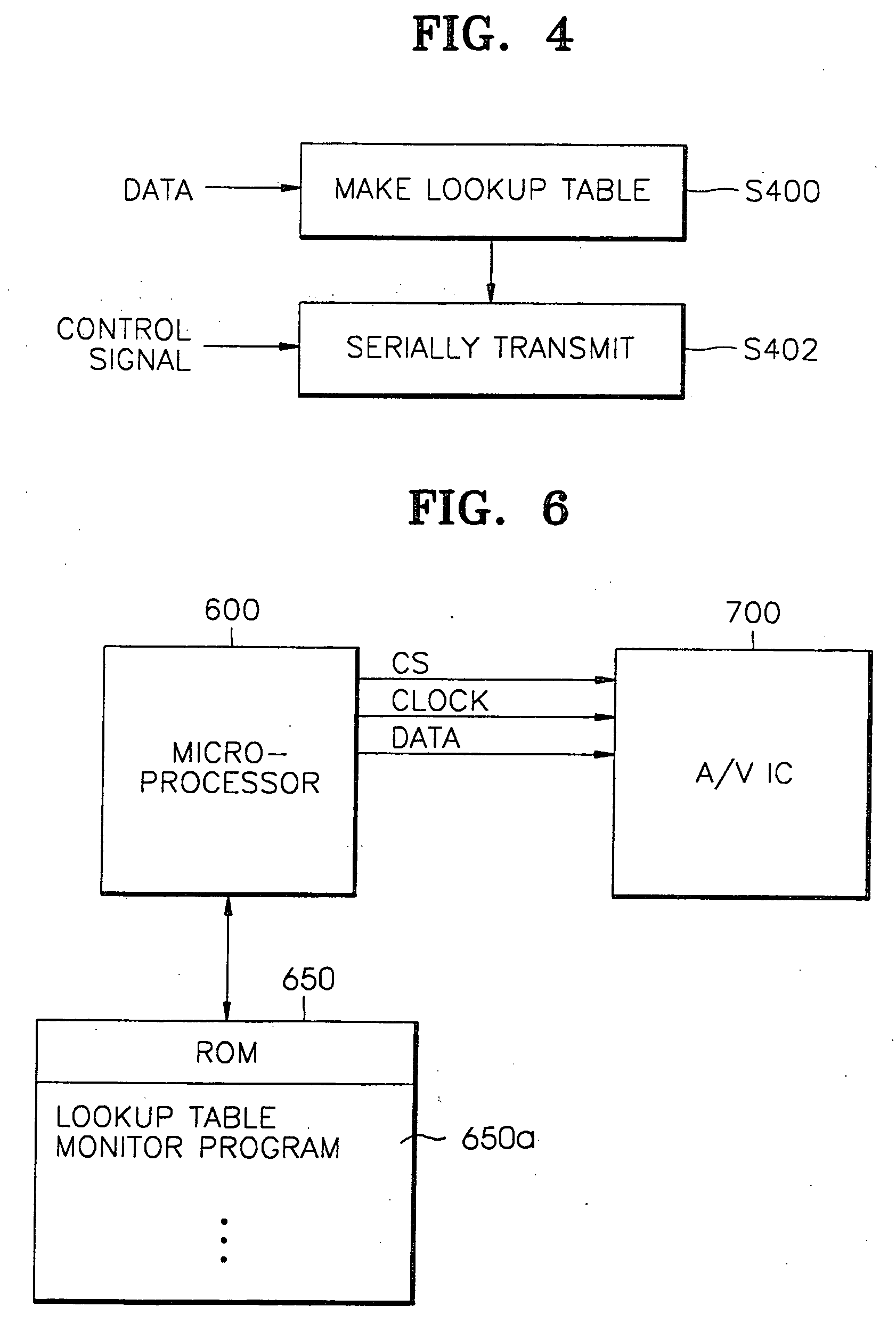
[0044]FIG. 6 is a block diagram for illustrating a control signal transmitting apparatus according to the present invention. The apparatus shown in FIG. 6 corresponds to a case where a microprocessor 600 directly outputs mapped (or encrypted) control signals, and has a lookup table 650a implemented in software. This lookup table 650a is included in a program for controlling the microprocessor 600 and generally stored in a ROM 650. The microprocessor 600 obtains mapped control signals corresponding control states, from the lookup table 650a. The mapped control signals together with a clock signal (CLK) and a chip enable signal (CS) are transmitted to the A / V IC 700.

[0045]FIG. 7 illustrates the format of data transmitted in a method for transmitting a control signal according to both embodiments of the present invention. A chip select signal (CS) is shown at the top of FIG. 7, a clock signal is shown at the center of FIG. 7, and data, that is a mapped control signal, is shown at the b...


PUM


Abstract

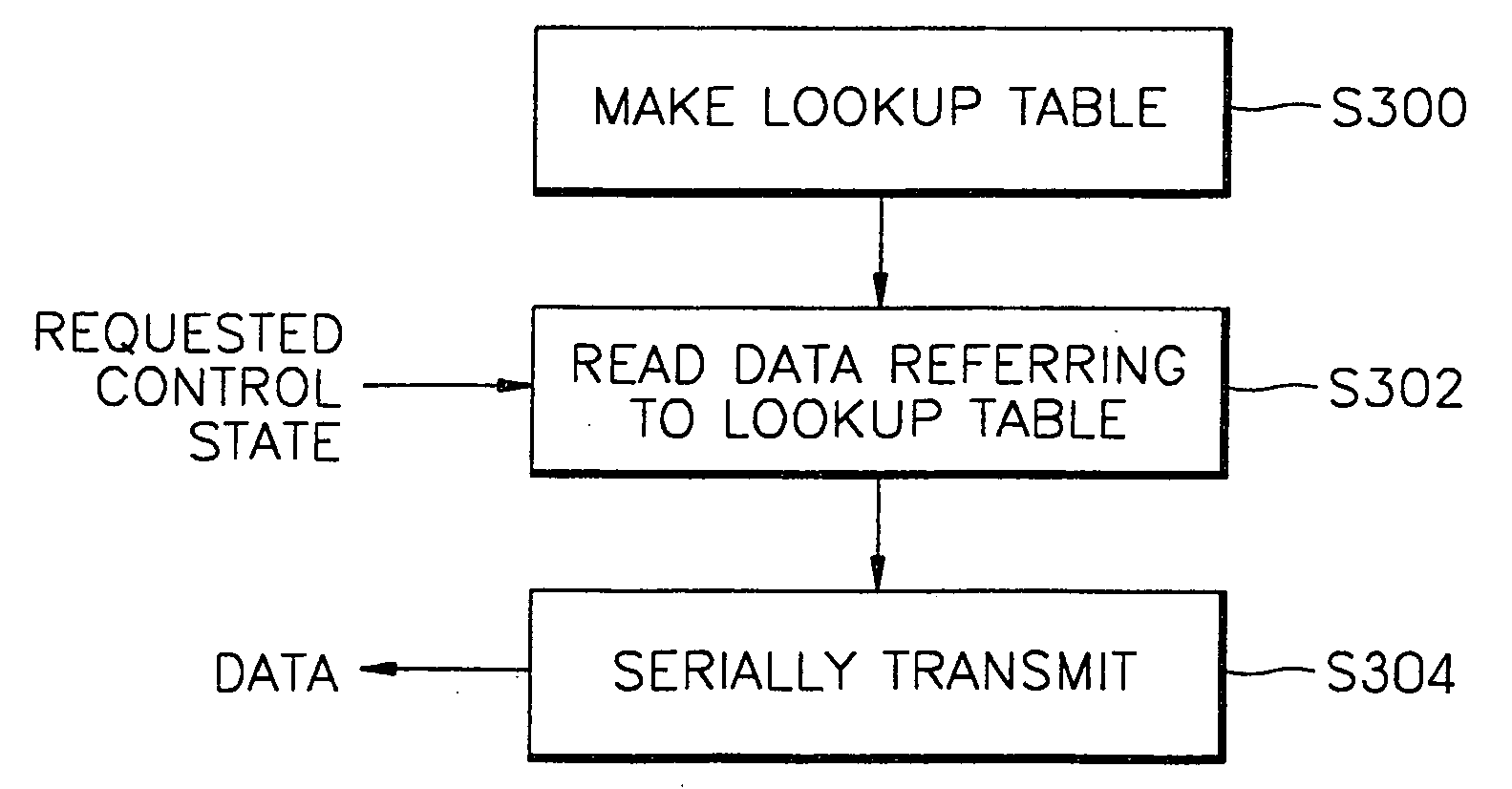
Control signal transmitting and receiving methods for video / audio processing integrate circuit (IC), the method applied to a video player, and an apparatus therefor are provided. The control signal transmitting method, in a video player having an integrated circuit (IC) for processing video / audio signals and a microprocessor generating control signals to control the IC, has the steps of mapping serial data corresponding to possible control states of the video / audio signal processing IC, and storing the mapped data in a lookup table, reading serial data corresponding to a control state of the video / audio signal processing IC requested by the microprocessor, from the lookup table; and transmitting the serial data to the video / audio signal processing IC, being synchronized to a clock signal. Since in the control signal transmitting and receiving method the number of pins of an A / V IC decreases greatly compared to the conventional parallel transmitting and receiving method, the cost of manufacturing A / V ICs can be reduced to strengthen the competitiveness of products.

Description

CLAIM OF PRIORITY [0001] This application makes reference to, incorporates the same herein, and claims all benefits accruing under 35 U.S.C. § 119 from my application entitled Transmitting and Receiving Methods for Video / Audio Processing IC and Apparatus Therefor filed with the Korean Industrial Property Office on 31 Oct. 2000 and there duly assigned Ser. No. 2000 / 64215. BACKGROUND OF THE INVENTION [0002] 1. Field of the Invention [0003] The present invention relates to a video player, and more particularly, to control signal transmitting and receiving methods for video / audio processing integrated circuit (IC), the method applied to a video player, and an apparatus therefor. [0004] 2. Description of the Related Art [0005] An audio / video processing IC (A / V IC) is an integrated circuit for processing video / audio signals in a video player. An A / V IC chip has many blocks, such as an FM modulator, an FM demodulator, a noise remover, a luminance / color matrix, a recording equalizer, a repr...

Claims


Application Information

Patent Timeline
Patent Type & Authority Applications(United States)
IPC IPC(8): H04N9/475H04N5/44H04N9/87
CPCH04N9/87H04N5/44
Inventor KIM, CHUL-MIN
Owner SAMSUNG ELECTRONICS CO LTD
Learn More