
Lateral Tape Motion Detector

a motion detector and lateral tape technology, applied in the field of storage tape drives, can solve the problems of sensitivity limitation due to optical setup, affecting the accuracy and sensitivity of this type of measurement, and imperfect edges, so as to reduce noise and drift interference, increase detection sensitivity, and effective control signal

Active Publication Date: 2013-12-26
ORACLE INT CORP
View PDF2 Cites 3 Cited by
  • Summary
  • Abstract
  • Description
  • Claims
  • Application Information

AI Technical Summary

Benefits of technology

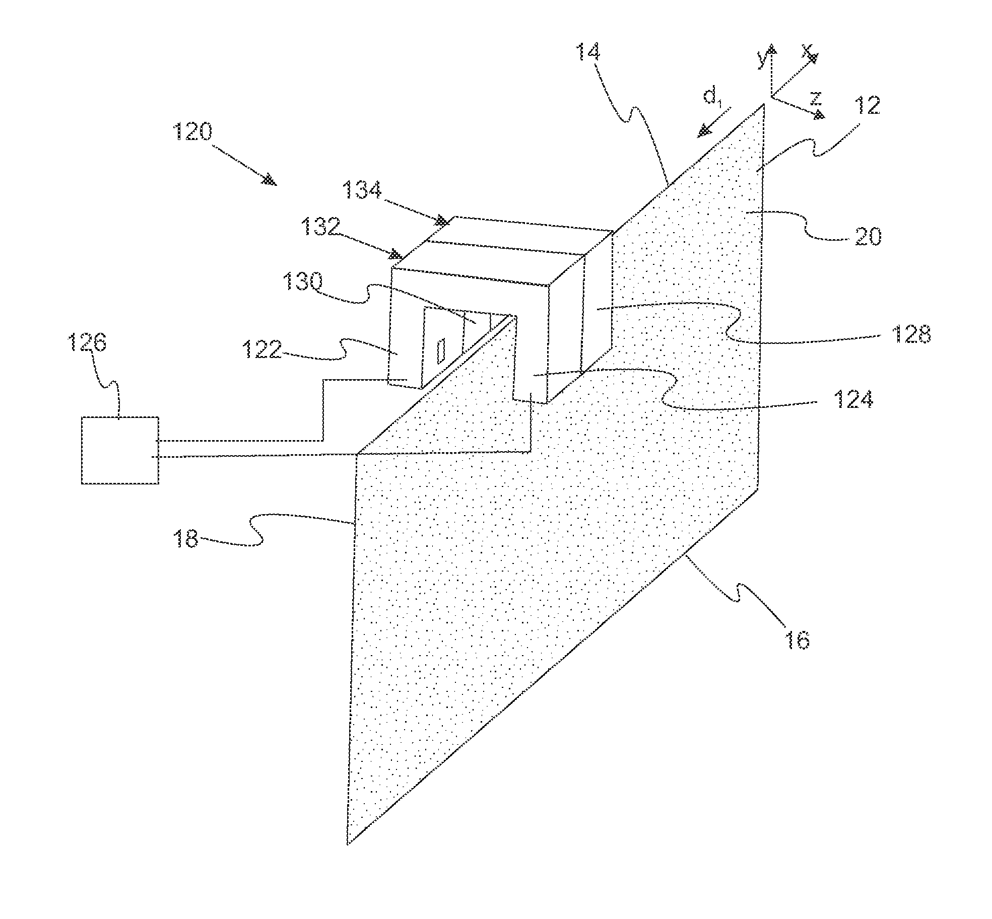
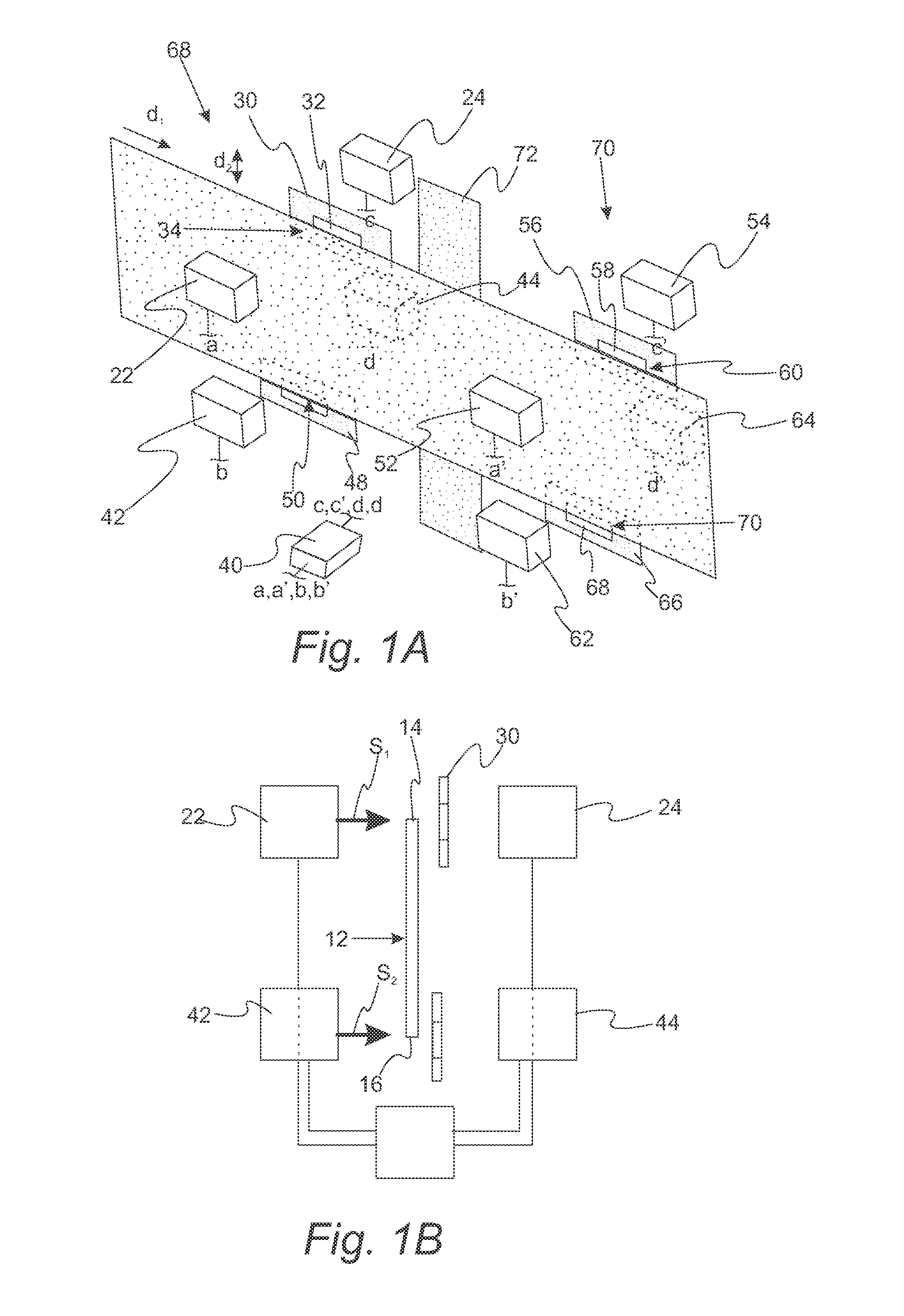
The present invention provides a tape edge sensor system for detecting lateral movement of a storage tape in a storage tape drive. This system increases detection sensitivity by reducing noise and drift interference. The use of four sets of sensor allows for information regarding lateral motion of the storage tape to be transmitted to a tape head's tracking servo which can provide a more effective control signal to reduce tracking error.

Problems solved by technology

The accuracy and sensitivity of this type of measurement, however, is severely impacted by several limitations.
Such limitations include imperfection of edge profile that incorrectly registers as LTM, sensitivity limitation due to optical setup, and electro-mechanical and optical noise and drift contamination
Lateral tape motion (LTM) is problematic in tape drives especially as track pitches get smaller and smaller in new generations of magnetic and optical tape drives.
As track pitches get smaller, for example, 320 nm in an optical tape drive, LTM measurements accurate to microns or tens of microns are no longer adequate.
To measure LTM, optical sensors, such as photonic probes and photo-interrupters, have been used but have characteristics that limit their accuracy and resolution to unacceptable levels compared to the 10 to 20 nm needed for newer, finer track pitches.
Unfortunately, photonic probes and photo-interrupters also have limited ability to change the sampling length of tape.

Method used


Image

  • Lateral Tape Motion Detector
  • Lateral Tape Motion Detector
  • Lateral Tape Motion Detector

Examples


Embodiment Construction

[0030]Reference will now be made in detail to presently preferred compositions, embodiments and methods of the present invention, which constitute the best modes of practicing the invention presently known to the inventors. The Figures are not necessarily to scale. However, it is to be understood that the disclosed embodiments are merely exemplary of the invention that may be embodied in various and alternative forms. Therefore, specific details disclosed herein are not to be interpreted as limiting, but merely as a representative basis for any aspect of the invention and / or as a representative basis for teaching one skilled in the art to variously employ the present invention.

[0031]Except in the examples, or where otherwise expressly indicated, all numerical quantities in this description indicating amounts of material or conditions and / or use are to be understood as modified by the word “about” in describing the broadest scope of the invention.

[0032]It is also to be understood tha...


PUM

PropertyMeasurementUnit
frequencyaaaaaaaaaa
lengthaaaaaaaaaa
widthaaaaaaaaaa

Abstract

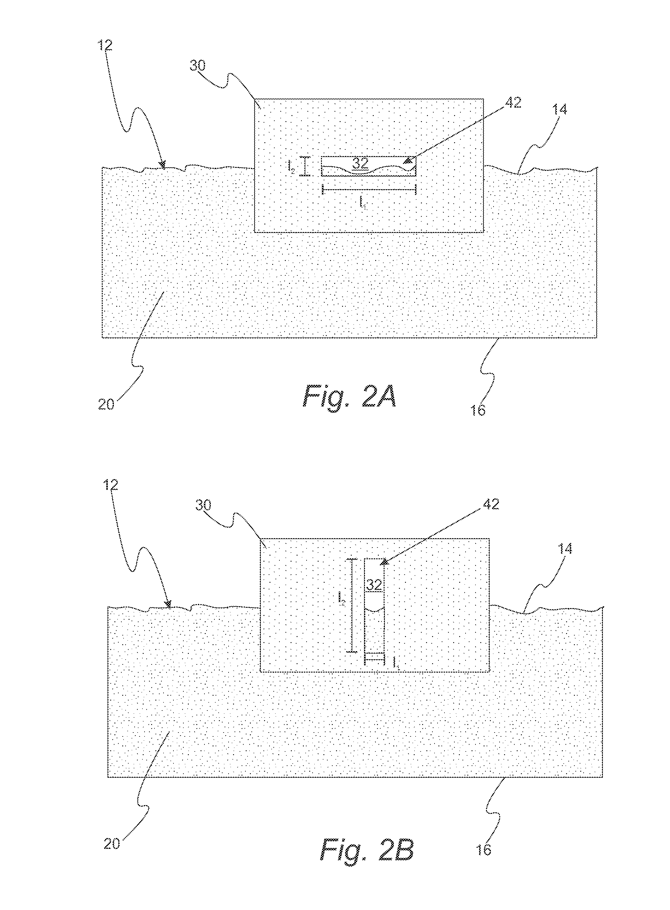
A tape edge sensor system for detecting lateral movement of a storage tape includes a first photo-emitter, a first photo-detector positioned to receive a first light signal from the first photo-emitter, a first aperture disposed between the first photo-emitter and the first photo-detector, and a feedback system connected to the first photo-emitter and the first photo-detector. The first aperture defines a first region at a first tape edge through which the first light signal is received by the first photo-detector with the storage tape blocking a portion of the first light signal. The feedback system determines the first photo-detector's signal amplitude and adjusts the first light signal such that the first photo-detector signal amplitude is within a first average amplitude range. A tape edge sensor system using compensating photo-interrupters is also provided.

Description

[0001]The present invention relates to systems and methods for detecting lateral tape movement in an optical or magnetic storage tape drive.BACKGROUND OF THE INVENTION[0002]In the storage tape drive industry, transmissive optical sensors have been used to measure the dynamic behavior of the edge of the tape traveling on a tape transport subsystem. This technique generally has been used to estimate lateral motion of the tape (LTM) at any location in the tape transport subsystem. The accuracy and sensitivity of this type of measurement, however, is severely impacted by several limitations. Such limitations include imperfection of edge profile that incorrectly registers as LTM, sensitivity limitation due to optical setup, and electro-mechanical and optical noise and drift contamination[0003]Lateral tape motion (LTM) is problematic in tape drives especially as track pitches get smaller and smaller in new generations of magnetic and optical tape drives. Magnetic and optical read / write he...

Claims


Application Information

Patent Timeline
Patent Type & Authority Applications(United States)
IPC IPC(8): G11B27/36
CPCG11B15/602G11B5/584G11B20/10388G11B2220/90B65H23/0216B65H2553/412B65H2701/11332B65H2701/1315
Inventor MAHNAD, FARAMARZWILSON, SCOTT D.
Owner ORACLE INT CORP
Learn More