Sensor Arrangement for Measuring a Pressure and a Temperature in a Fluid

Active Publication Date: 2007-05-31
SENSATA TECHNOLOGIES INC
View PDF20 Cites 53 Cited by
  • Summary
  • Abstract
  • Description
  • Claims
  • Application Information

AI Technical Summary

Benefits of technology

[0021] These features allow to reduce the effect of the flow of the fluid along the elongated body on the pressure measurement. The lateral movement of the closed end of the elongated body will result in an increased strain at the surface of the pressure sensitive structure at one side of the hole and a decreased strain at the surface of the pressure sensitive structure at the opposite side of the hole in the pressure sensitive structure. By dividing the strain gauges equally around the hole in the pressure sensitive structure, the increased strain and decreased strain at the outer side of the pressure sensitive structure could be measured simultaneously which allows to compensate in the electronic circuitry the effect in the pressure measurement due to the lateral movement of the closed end of the elongated body.
[0022] In an embodiment of the invention the temperature sensitive electrical element is coupled to the membrane structure by means of a thermal conductive compound, like a gel. This feature allows to have a good thermal coupling of the temperature sensitive electrical element with the membrane structure. Furthermore, the compound in the form of a gel allows the temperature sensitive electrical element to have some movement with respect to the membrane structure. Variations of the pressure in the fluid will result in an axial movement of t

Problems solved by technology

Furthermore, using one metallic membrane to pass on both temperature and pressure reduces the poss

Method used


Image

  • Sensor Arrangement for Measuring a Pressure and a Temperature in a Fluid
  • Sensor Arrangement for Measuring a Pressure and a Temperature in a Fluid
  • Sensor Arrangement for Measuring a Pressure and a Temperature in a Fluid

Examples


Embodiment Construction

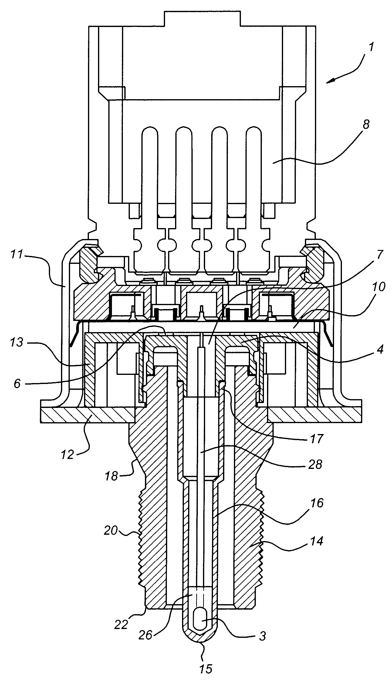
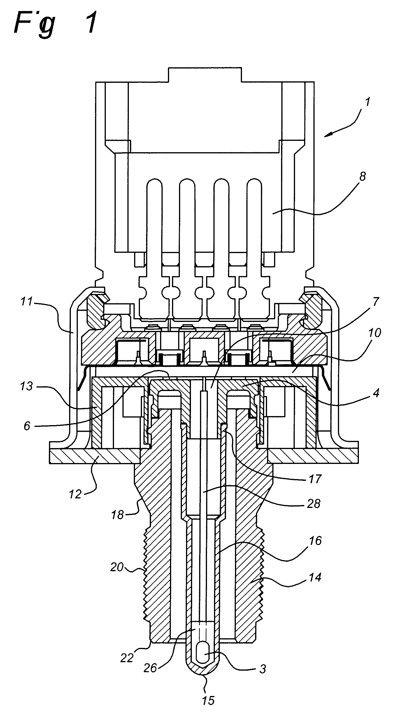
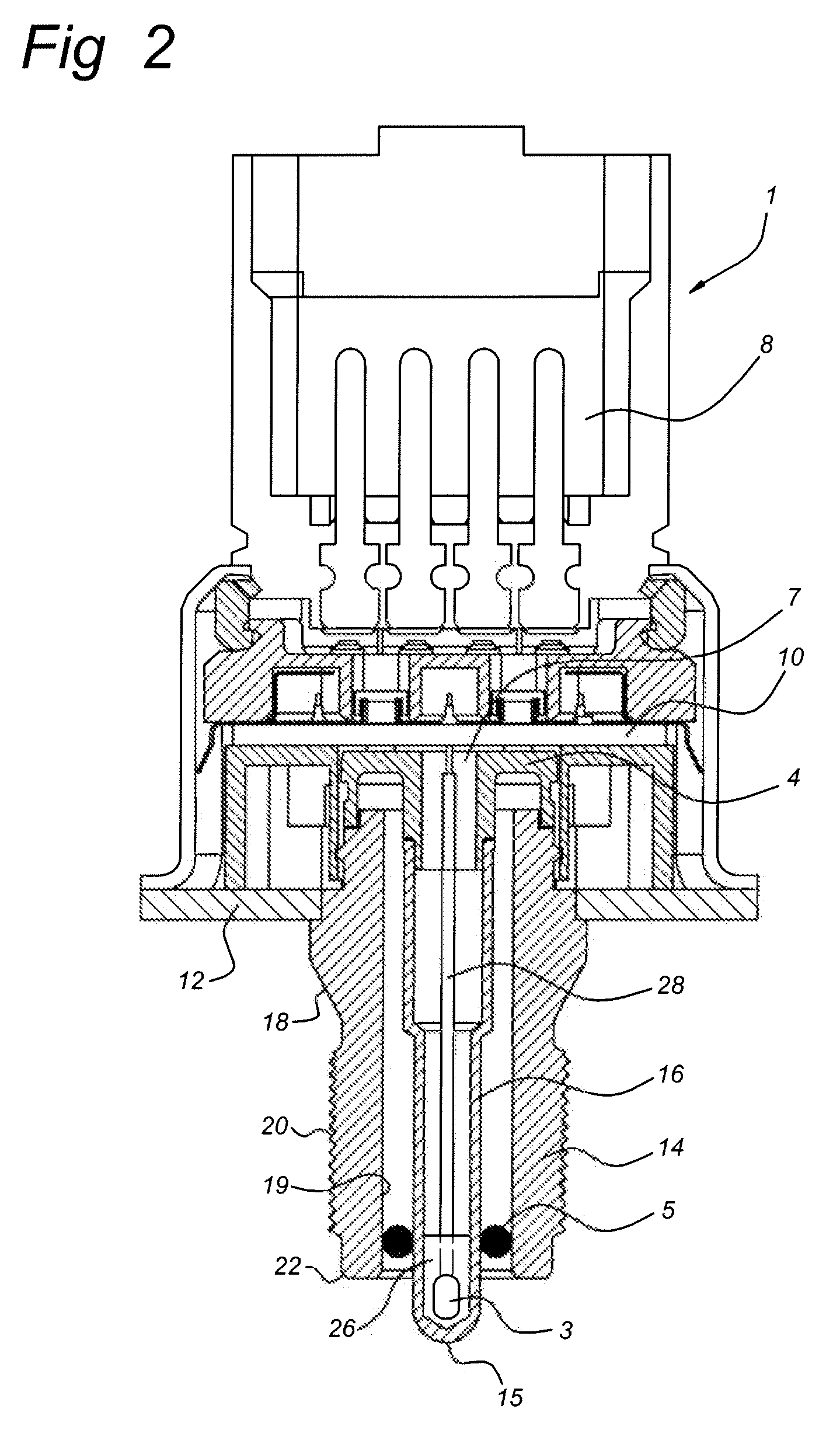
[0035]FIG. 1 illustrates a sectional view of a first embodiment of a sensor arrangement according to the present invention. The sensor arrangement 1 comprises a membrane structure 4, 16 both arranged in a common body 11, 12, 14. The membrane structure 4,16 includes an elongated body 16 and a pressure sensitive structure 4. The elongated body could be in the form of a metal tube, which is hermetically closed at one end. A temperature sensitive electrical element 3 is located at a closed end 15 of the elongated body 16. FIG. 6 shows a perspective view of the elongated body 16.

[0036] The temperature sensitive electrical element 3 could be any suitable Resistance Temperature Detectors (RTD), thermo couple or thermistor such as an NTC resistor. In order to measure accurately the temperature of the fluid, the closed end 15 of the elongated body 16 surrounding the temperature sensitive electrical element 3 should be immersed in the fluid to create a direct contact area with the fluid. Pre...


PUM


Abstract

A sensor arrangement (1) for measuring a pressure and a temperature in a fluid is disclosed. The sensor arrangement (1) comprises a temperature sensitive electrical element (3) and a pressure sensing electrical element (6), the temperature sensitive electrical element (3) and pressure sensing electrical element (6) are both coupled to one side of a metallic membrane structure (4,16). The metallic membrane structure is arranged to pass on the temperature of the fluid which is at the other side of the membrane structure (4,16) to the temperature sensitive electrical element (3) and to pass on the pressure in the fluid to the pressure sensing electrical element (6). In this way a combined pressure and temperature sensor is obtained which is applicable in vehicle air-conditioning systems working with CO2 as refrigerant.

Description

Related Applications [0001] Priority is claimed under European Patent Application No. 05111427.0, filed Nov. 29, 2005 and European Patent Application No. 06123975.2, filed Nov. 14, 2006. [0002] 1. Field of the Invention [0003] The present invention relates generally to a sensor arrangement for measuring a pressure and a temperature in a fluid. The sensor arrangement comprising a temperature sensitive electrical element and a pressure sensing electrical element. The invention has particular application in vehicle air-conditioning systems working with CO2 as refrigerant. The arrangement according to the invention is also suitable for use in fuel injection systems in automotive applications. [0004] 2. Background of the Invention [0005] Today's, vehicle air conditioning systems working, with the refrigerant R134a, exhibit a pressure sensor on the “high pressure side” after the compressor usually for monitoring the operating pressure and for control. If the operating pressure exceeds a g...

Claims


Application Information

Patent Timeline
IPC IPC(8): G01K1/14G01K1/16
CPCF25B2309/061F25B2700/19G01K13/02G01K2201/02G01L9/0051G01L19/003G01L19/0092G01L19/14
Inventor GENNISSEN, PAULUSBORGERS, MARCKOLLING, ARIE-JANZWOLLO, CRISAPPELO, ROGERKLEISSEN, WERNER
Owner SENSATA TECHNOLOGIES INC
Why Eureka
Try Eureka